Metal–insulator phase transition and topology in a three-component system*
Shujie Cheng(成書杰) and Xianlong Gao(高先龍)
Department of Physics,Zhejiang Normal University,Jinhua 321004,China
Keywords: band structures,high Chern numbers,bulk-edge correspondence
1. Introduction
Quantum Hall effect is discovered under the condition with a low temperature and strong magnetic fields.[1]Since this finding,enormous attention has been poured into the study on the topological properties of the quantum systems,[2–4]particularly on those quantum-engineered systems with quantum anomalous Hall effect(QAHE),[5–10]which are free from the extra magnetic fields.
One class of insulators realizing the QAHE breaking the time reversal symmetry,[11]is Chern insulator in condensed matter physics. Their topological properties are directly characterized by the Hall conductance first proposed by Thouless–Kohmoto–Nightingale–den Nijs (TKNN) in a twoband system.[12]Through TKNN’s work, we know that the mathematical concept of Chern number (C) plays an important role in the topology of Bloch systems. That is,a separated Bloch band corresponds to a well-defined Chern number. In a multiple-band system,the associated Chern number is equal to the quantized Hall conductance in unit of e2/h for the lowest occupied band,which determines the topological phases of the system. For instance,the nonzero C is indicative of a nontrivial phase,whereas C=0 is of a topologically trivial phase,demonstrating that the system is a normal insulator.For multiple occupied bands,although the Chern number is not directly related to the Hall conductance, the summation of the Chern numbers corresponding to these bands finally share the same value of the observable quantized Hall conductance.[13]
In the topological classification, Chern insulator belongs to the topological class A.[14]In general,it is possible to geometrically engineer a Chern insulator with arbitrary topological index C. In addition, higher Hall conductance is accompanied by larger C with reducing channel resistance in the field of interface transport, possessing more potential for applications. However,in materials,such as the magnetic topological insulators[15–21]and the magic-angle twisted bilayer graphene[22,23]which have been prepared with the QAHE,the observed Chern number is only C=1. Although it was studied that there were topological phases with C=2 in thin MnBi2Te4flakes[24]and in moir′e superlattice,[25]there were no well-defined landau levels, and an external magnetic field was required.
Beyond the investigations of QAHE in synthetic materials, optical-lattice experiments have the advantage of being highly flexible and adjustable, offering a platform for manipulating trapped ultracold atoms to realize the topological non-trivial phases. Accordingly,some attention has been paid to the optical-lattice experiments in recent years.[5–9,26–36]With the benefits of quite a few efforts,[5–9,29,32,37–39]two quintessential models with rich topological phenomena, i.e.,Haldane model[33,40]and Haper–Hofstadter model[34,41]have been well implemented. These mature techniques have had a significant impact on subsequent researches[42–49]and will increase the feasibility to realize the higher Hall conductance or larger Chern number with QAHE.
Recently, it was studied that there were topological nontrivial bands with C=-2 in a dice lattice model which is synthesized by Raman lasers.[50]Meanwhile,large Chern number phases with C =-3 were uncovered in a shaken dice optical lattice.[51]In this paper, we are motivated to study a noninteracting model on the three-component dice lattice[50–59]with real nearest neighbor and complex next-nearest neighbor hopping under Λ- or V-shaped sublattice potentials. We mainly focus on the 1/3 filling and 2/3 filling cases, corresponding to the lowest band occupied and lower two bands occupied, respectively. By analyzing the band structures, we find that the system will have two kinds of phases, metallic phase and bulk insulating phase, thus, experiencing a metal–insulator phase transition. The metal–insulator phase diagram is plotted in the Δ–φ parameter space, with Δ being the strength of the tunable on-site potentials and φ the phase of the next-nearest-neighbor hopping. Further, we investigate the topological properties in the bulk insulating phase.Results suggest that there exist non-trivial topological phases with Hall conductance equal to±1,±2,in units of e2/h. Furthermore,the quantization of the Hall conductance can be seen from the edge-state energy spectra and the large Chern numbers are self-consistently analyzed by the principle of bulkedge correspondence.[60]
The paper proceeds as follows. Section 2 describes the model and its Hamiltonian in both the real and momentum space. Section 3 contains the analysis of the band structures,the topological phases, as well as the edge-state spectra and Chern numbers. Section 4 summarizes the results of these investigations.
2. Model and Hamiltonian
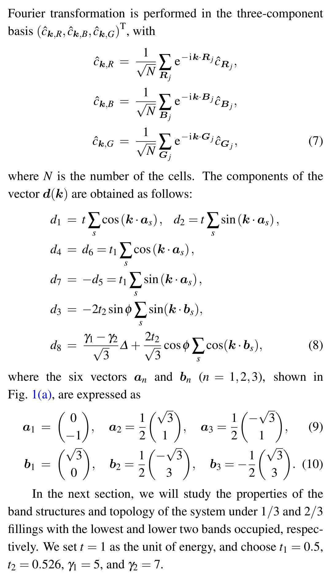
In this paper,we consider a non-interacting model based on the dice lattice,as shown in Fig.1,with three interpenetrating triangle sublattices[denoted by R(red dots),B(blue dots),and G (green dots)]. The single-particle Hamiltonian of the model consists of three terms
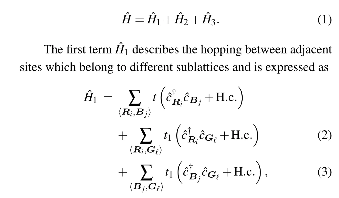
where t is the hopping amplitude between adjacent R sites and B sites, t1is the real hopping amplitude between adjacent R(or B) and G sites, ?cRi,?cBj, and ?cG?are the corresponding fermionic annihilation operators defined on the relevant sites Ri,Bj,and G?of sublattices R,B,and G,respectively. 〈···〉means the nearest-neighbor hopping.
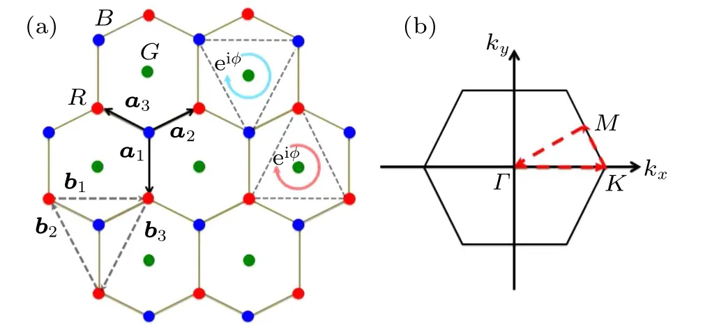
Fig.1. (a)The schematic diagram of the three-band Λ-or V-type dice model.The red,blue,and green dots denote the R,B,G sublattice sites,respectively.The vectors an (n=1,2,3) connect the nearest neighbors which belong to different sublattices. The vectors bn (n=1,2,3)connect the nearest neighbors which belong to the same R and B sublattice sites. The circle arrows show the direction of hopping with a phase factor φ in eiφ. (b) The first Brillouin zone. Γ,K,and M are high-symmetry points which are connected by three red dashed arrows. The distance between adjacent sites has been set as unit length.
3. Results and discussion
3.1. Band structures
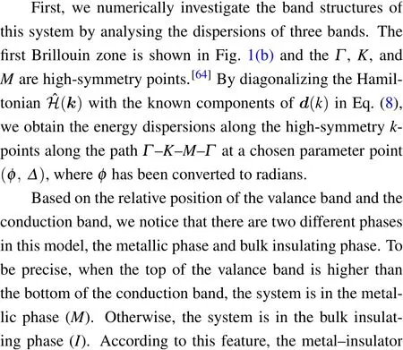

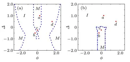
Fig.2. Δ–φ phase diagram for the case of 1/3 filling(a)and 2/3 filling(b).The metallic phase (M) is separated from the bulk insulating phase (I). In each case, we choose four typical parameter points a, b, c, and d discussed in details in the main text. For 1/3 filling,system is in the metallic phase at the a point,while it is in the bulk insulating phase at the b and d points. The opposite is obtained for the ones at 2/3 filling. For the c(d)point,the system is always in the metallic(insulating)phase,no matter what the filling is.
In order to comprehend these two phases intuitively, we plot the dispersion relations of the three bands at the four chosen parameter points (φa, Δa), (φb, Δb), (φc, Δc), and(φd, Δd),as shown in Figs.3(a),3(b),3(c),and 3(d),respectively. In each diagram,we select two Fermi energies for reference,corresponding to the case of 1/3 filling(magenta dotdashed line) and 2/3 filling (green dashed line), respectively.The red, blue, and black solid lines represent the dispersions of the bands ranging from the bottom to the top,respectively.In Fig.3(a),when the Efis chosen at 1/3 filling,the fully occupied bottom band and a partially occupied middle band lead to a metallic phase,although the middle and the bottom band avoid touching each other. When the Efis tuned up to 2/3 filling,there is a significant band gap between the top and the middle band,leading to a completely empty conduction and a fully occupied valence band. Therefore, the system is in the bulk insulating phase for 2/3 filling. With the same reasons,it is not difficult to interpret that the system is in the bulk insulating phase at 1/3 filling, and in the metallic phase at 2/3 filling for the case shown in Fig. 3(b). Moreover, the system is always in the metallic phase shown in Fig. 3(c) and in the bulk insulating phase shown in Fig.3(d),respectively,no matter what the filling is. All these are manifested in the metal–insulator phase diagrams in Fig. 2. In the following, we will further investigate the topological properties in the Δ–φ phase diagram.
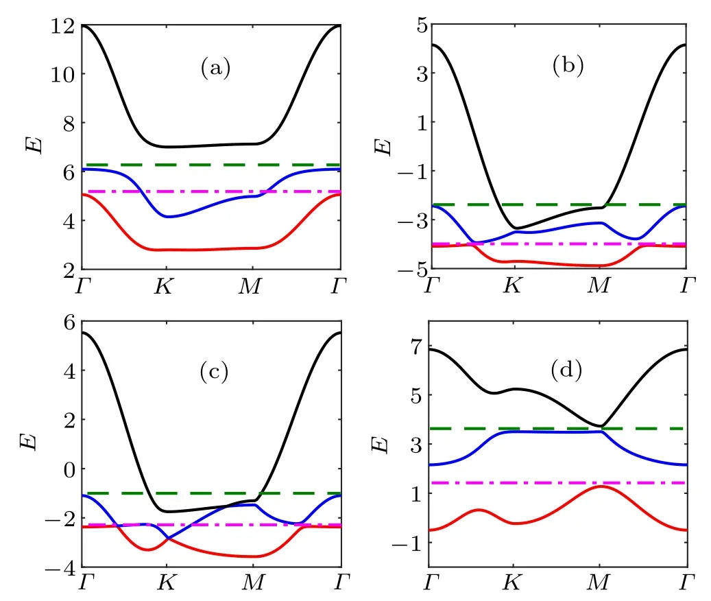
Fig. 3. Dispersion relations of the three bands along the high-symmetry kpoints along the path Γ–K–M–Γ. The red,blue,and black lines correspond to the dispersion relations of the three bands from the bottom to the top,respectively. (a) φa =0.25, Δa =1; (b) φb =-0.25, Δb =-0.5; (c) φc =0,Δc=-0.25;(d)φd =π/2,Δd =0.5. The lower Fermi energy(magenta dotdashed line)and higher Fermi energy(green dashed line)correspond to the case of 1/3 and 2/3 filling,respectively.
3.2. Topological phases
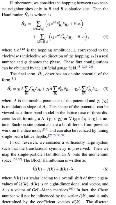
Motivated by the Haldane model[40]and the dice models,[50,51]we try to understand whether there are any topological properties in the bulk insulating phase or not. For the three-band system considered, when Efis within a band gap,the Hall conductance[12]can be defined as

where Cnis Chern number of the n-th fully occupied band and is expressed as

where n ∈{1,2,3}is the band index and its ascending order corresponds to three energy bands from bottom to top; ?BZ is the boundary of the first Brillouin zone; Anis the Berry connection with An=-i〈ψn(k)|?k|ψn(k)〉 and |ψn(k)〉 is the corresponding eigenvector. Without loss of generality,we use two quantities,C1/3and C2/3,to character the topological properties under 1/3 and 2/3 filling, respectively. The relationship between the topological number of the filling (C1/3,C2/3) and band Chern numbers (C1and C2) is that C1/3=C1and C2/3=C1+C2.
The topological Δ–φ phase diagram is obtained as shown in Figs.4(a)and 4(b)by calculating the C1/3and C2/3,corresponding to the topological numbers for the 1/3 and 2/3 filling of the system, respectively. In Fig. 4, there are several phase boundary lines shown in red and black dashed lines in the bulk insulating phase, accompanied by energy band closing.[40,65]In fact, the band crossing lines also appear in the metallic phase without changing the intrinsic properties being a metal.Particularly,in each diagram,the topological non-trivial phase is separated from the topological trivial one by the red dashed lines,whereas the topological non-trivial phases are separated from the different nonzero Chern numbers by the black dashed lines.
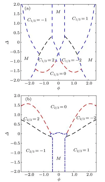
Fig. 4. The topological Δ–φ phase diagram for the (a) 1/3 filling and (b)2/3 filling, respectively. The Chern numbers have been marked in these two diagrams. Except for the metallic phase (M) surrounded by the blue dashed lines intersected with the coordinate axes,the bulk insulating phase is divided into several regions by red dashed lines which distinguish the topological non-trivial phase from the topological trivial one, and by black dashed lines which separate the topological non-trivial phases with different Chern numbers.
From the phase diagrams,we can see intuitively that there are abundant quantum phases in the system. In Fig.4(a), besides the metallic phase regions, there are topological nontrivial phases with C1/3=±1 and C1/3=±2, as well as the topological trivial phase with C1/3=0. Moreover, when we tune the parameters continuously, the system goes through rich different phases. For instance, when Δ =-0.25, as φ increases,the system will circularly undergo six phases:
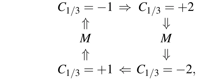
where M is short for the metallic phase.When Δ=0.5,system will cycle through five phase regions by increasing the φ:

Similarly,for fixing φ,the system experiences with rich phases when we change the tunable parameter Δ of the potential.
3.3. Edge states and Chern numbers
According to the research in Ref.[13],we know that the quantization of the Hall conductance or the total Chern number can be readily seen from the edge-state spectrum in static systems,known as the bulk-edge correspondence. In this subsection, we study the bulk-edge correspondence by considering a cylindrical geometry with a periodic boundary condition in the x direction and an open boundary condition in the y direction. Two types of lattice geometries with zigzag and armchair edge are studied, shown in Figs. 5(a) and 5(b), respectively, surrounded by the dashed boxes representing the periodic repeating units, each of them containing Nzigzagand Narmchairlattice sites. The Hamiltonian ?H(kx) used for calculating the energy spectrum Ekxcan be treated as a function of the good quantum number kx.

Fig.5. The two schematic diagrams of the system with a periodic boundary condition in the x direction and an open boundary condition in the y direction. The two types of boundaries are studied: (a) the zigzag edge and (b)the armchair egde. The lattice structures surrounded by the black dotted lines represent the periodic repeating units which contain Nzigzag and Narmchair lattice sites,respectively.
By choosing Nzigzag=299 and Narmchair=243, two associated edge-state spectra at the parameter point(φd, Δd)=(π/2, 0.5)are calculated,as shown in Figs.6(a)and 6(b),respectively. Intuitively, there is a pair of edge modes at 1/3 filling corresponding to a topological non-trivial phase with C1/3=1, and two pairs of edge modes at 2/3 filling corresponding to a topological non-trivial phase with C2/3=-2 with no dependence on the edge of the system.
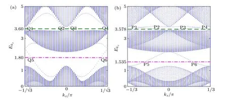
Fig.6. Two edge-state spectra of the system with a periodic boundary condition in the x direction and an open boundary condition in the y direction at the parameter point(φd,Δd)=(π/2, 0.5). Magenta dot-dashed and green dashed lines denote the chosen Ef for 1/3 filling and 2/3 filling,respectively.(a)Edge-state spectra for the zigzag-edge case. Q5 and Q6 are a pair of edge mode at Ef=1.80 for 1/3 filling;Q1 and Q4,Q2 and Q3 are two pairs of edge modes at Ef=3.60 for 2/3 filling.(b)Edge-state spectra for the armchair-edge case.P5 and P6 are a pair of chiral edge modes at Ef=1.535 for 1/3 filling;P1 and P4,P2 and P3 are two pairs of edge modes at Ef=3.578 for 2/3 filling. The results indicates that,no matter what kind of edge the system has,there is a pair of edge modes at 1/3 filling corresponding to C1/3=1,and two pairs of edge modes at 2/3 filling corresponding to C2/3=-2.
As the principle of the bulk-edge correspondence tells,[60]Chern number is closely related with the chiral edge modes.To be concrete, the Chern number of a band is equal to the sum of the Chern numbers of the edge modes above the band minus that of edge modes below the band. Particulary, these chosen edge modes should be located at the same edge. By choosing the same parameters used for edge-state spectra,we plot the spatial density distributions of the edge modes of Q1–Q6 in the zigzag-edge case and the edge modes of P1–P6 in the armchair one, in Fig. 7. We first analyze the zigzag-edge case. As the distributions show(up panels in Fig.7), Q5 and Q6 are a pair of chiral edge modes at Ef=1.80 for 1/3 filling;Q1 and Q4,Q2 and Q3 are two pairs of chiral edge modes at Ef=3.60 for 2/3 filling. In particular,the spatial density distributions of the edge modes with positive group velocity are shown in red, while black for those with the negative group velocity. We analyze the Chern number by means of the edge modes localized at the site of j=Nzigzag. From the above calculation, C1/3=1, that is, the edge mode Q5 carries C=1.Naturally, we know that the edge modes Q3 and Q1 with the opposite group velocity both carry C=-1. Accordingly, we get C1=1 and C2=-1+(-1)-1=-3.
For the armchair-edge case,there are also six edge modes marked as P1–P6,in which P5 and P6 are a pairs of chiral edge modes at Ef=1.535(magenta dot-dashed line),P1,P4 and P2,P3 are another two pairs of chiral edge modes at Ef=3.578(green dashed line). We notice that the edge mode P6 localized at the site of j=Narmchairthe armchair case has the same sign of the group velocity as the edge mode Q5 of the zigzag case. Hence,P6 carries C=1,which leads to C1=1. Meanwhile,the edge modes P1 and P3 with positive group velocity both carry C=-1,thus C2=-1+(-1)-1=-3. All these analyses are self-consistent with the phase diagrams in Fig.4.
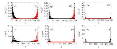
Fig. 7. Spatial density distributions of the edge modes. Top panel: the zigzag-edge case. The result shows that, Q5 and Q6 are a pair of chiral edge modes at Ef =1.80 for 1/3 filling;Q1 and Q4,Q2 and Q3 are two pairs of chiral edge modes at Ef =3.60 for 2/3 filling. The label j is the site index of the periodic repeating unit as shown in Fig. 5(a), as an artificial chain with the order of B–R–G–···–B–R. Bottom panel: the armchair-edge case.Intuitively, P5 and P6 are a pair of chiral edge modes at Ef =1.535 for the 1/3 filling; P1 and P4, P2 and P3 are two pairs of chiral edge modes at Ef=3.578 for the 2/3 filling. The label j denotes the site index of the periodic repeating unit as shown in Fig.5(b),as an artificial chain with the order of R–B–G–R–G–B–···–R–G–B–R–B–G. Particularly,the distributions of the edge modes with positive group velocity are shown in red,whereas black for negative one.
4. Conclusion
In conclusion,we have studied the three-band dice model which is composed of three types of sublattices. Firstly, we investigated the dispersion relations of the energy bands, and found that the system has the metallic and bulk insulating phase. The metal–insulator phase diagrams were plotted in the Δ–φ parameter space. Further, we evaluated the Chern numbers through the energy band theory in the bulk insulating phase. Interestingly,high Hall plateau was uncovered with C1/3=±2 (C2/3=±2). The quantizations of the Hall conductance were readily seen in the edge-state spectra. Finally,we verified the Chern numbers through the spatial density distributions of the edge modes according to the principle of the bulk-edge correspondence.
Although the similar lattice structure has been studies in several electronic materials,[66–70]due to the high tunability of the parameters in the cold-atom experiments,it is now possible for experimentalists to research topological phases of neutral atoms which never appear in these aforementioned researches.Thus,we hope that the system with high Hall plateau proposed here can be realized in the near-future cold-atom experiment.
- Chinese Physics B的其它文章
- Numerical simulation on ionic wind in circular channels*
- Interaction properties of solitons for a couple of nonlinear evolution equations
- Enhancement of multiatom non-classical correlations and quantum state transfer in atom–cavity–fiber system*
- Protein–protein docking with interface residue restraints*
- Effect of interaction between loop bases and ions on stability of G-quadruplex DNA*
- Retrieval of multiple scattering contrast from x-ray analyzer-based imaging*

