Investigation on the streamer propagation in atmospheric pressure helium plasma jet by the capacitive probe
Wenchao ZHU(朱文超),Bangdou HUANG(黃邦斗),Ximing ZHU(朱悉銘),Wencong CHEN (陳文聰) and Yikang PU (蒲以康)
1 State Key Laboratory of NBC Protection for Civilian,Institute of Chemical Defense AMS,Beijing 102205,People’s Republic of China
2 Department of Engineering Physics,Tsinghua University,Beijing 100084,People’s Republic of China
3 Key Laboratory of Power Electronics and Electric Drive,Institute of Electrical Engineering,Chinese Academy of Sciences,Beijing 100190,People’s Republic of China
4 Harbin Institute of Technology,Harbin 150001,People’s Republic of China
Abstract
Keywords:streamer propagation,capacitive probe,guided ionization waves
1.Introduction
The atmospheric pressure plasma jet (APPJ) has attracted significant attention for their potential application in material processing and biomedicine[1–4].APPJ can be generated by a dielectric capillary tube with one or two electrodes,which are driven by kilohertz AC or pulsed DC power supply[5–11].By high-speed photographs with intensified chargecoupled device,this kind of APPJ generates ‘guided ionization wave’ with a velocity in the range of 104–105m s-1[12],which cannot be explained by the Townsend mechanism[13,14].The plasma morphology or shape could be the‘donuts shape’ [15].The characteristics of the guided ionization wave have been investigated by the optical emission diagnostics [16]and the numerical simulation [10].Recently,experimental work on the temporal electrical characteristics of the guided ionization waves involving in the streamer mechanism has been reported [17,18],since the differences between the streamer and Townsend theory are mainly caused by the electric field induced by the net space charges in the streamer head.In this work,aimed at verifying the applicability of the streamer propagation mechanism to the guided ionization waves,the propagation velocity and the current signal induced by the net space charges in the APPJ are measured by using the capacitive probe in the discharge configuration with a floating electrode nozzle.Based on the streamer propagation mechanism,the physical scenario of the whole discharge process of this kind of plasma jet is revealed.
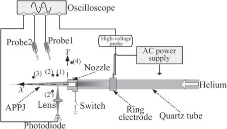
Figure 1.Schematic of the experimental setup.
2.Experimental setup
Figure 1 shows the experimental configuration.The helium with the flow rate of 1.6 l min-1flows through a cylindrical quartz tube with a 4 mm inner diameter and a 6 mm outer diameter.A floating bare metal electrode with a 1.2 mm diameter hole is mounted at the tube end as a nozzle.The nozzle is connected to the ground by controlling a switch.When the switch is open,the nozzle works as a floating ground electrode,otherwise,the nozzle works as the grounded electrode.A copper ring electrode is located 25 mm away from the nozzle and is powered by a sinusoidal high voltage with a frequency of 10.12 kHz.The applied voltage is measured by a highvoltage probe (Tektronix P6015A).A photodiode (OPT 210)with 900 kHz bandwidth and a lens with a 25 mm focus are used to measure the temporal emission of the jet at a fixed location (5.5 mm away from the nozzle,X=5.5 mm).
The capacitive probe method,which has been introduced in[19,20],can be used to measure the propagation velocity and the space charge of the guided ionization waves.The simplified capacitive probe is made of a 50 Ω coaxial cable with a BNC(Bayonet Neill-Concelman) connector.A protruding internal conductor of the cable with a 10 mm length and 1 mm diameter is used as the probe tip,which is perpendicularly placed 8 mm away from the plasma region.The signal is recorded by an oscilloscope (Tektronix TDS 540,with a bandwidth of 500 MHz and the sampling rate of 1 GHz)at 50 Ω terminal via the cable.Figure 2 shows the photo of the capacitive probe.In the experiments,the probe tip is placed vertically above the plasma jet.Displacement current signal will be generated when space charges in guided ionization wave pass through the probe tip.Thus,the amount of the net space charges could be obtained.
According to the Maxwell’s equations,the displacement current can be expressed as

where ε is the dielectric constant of the gas,and E is the electric field.Since the electric field E is related by the net space charges Q by
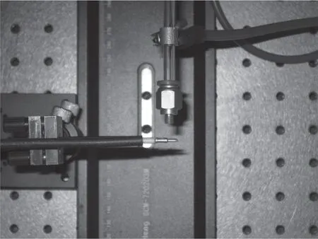
Figure 2.Photo of the capacitive probe.

The change in net space charge distribution with time results in a displacement current.Thus,the capacitive probe yields a current signal related to the presence of a charge density,which can be represented as

wherefdis the space sensitivity of the probe [19].The temporal signal of the probe is measured by an oscilloscope with a fixed input impedance of 50 Ω and 10 pF,which has a 0.5 ns effective RC-time constant.
3.Results and discussion
As shown in figure 3(a),when the voltage on the power electrode is 6.2 kV,only a dielectric barrier discharge (DBD) is generated between the two electrodes.Accordingly,only one pulse is measured by the capacitive probe in the positive half period,and we call this current pulse as the ‘nozzle current pulse’(Inozzle).No emission signal is detected by the photodiode.
When the voltage on the power electrode exceeds 6.4 kV,a plasma jet will emerge from the nozzle,as seen in figure 3(c).In this case,another current pulse is measured several microseconds after the first one in the positive half period,and we call the second current pulse as the ‘jet current pulse’ (Ijet).A burst of optical emissions is also detected by the photodiode.We aligned two detectors along the vertical(Y)direction at the location (2) and (2'),respectively,to calibrate the time delay.Both the peaks of Inozzleand Ijetof the two probes are at the same time,as shown in figures 3(b) and (d).
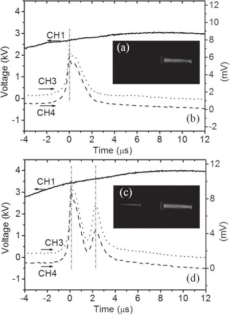
Figure 3.The photos of the DBD discharge (a) and the plasma jet discharge (c),and the corresponding signals ((b) and (d)) of the voltage probe (CH1)and the two capacitive probes (CH3 and CH4)at a same X position.
Inozzleis induced by the charge (Qf) accumulated on the floating nozzle,since the charge flowing into the floating nozzle during the DBD discharge cannot flow away to the ground directly.The presence of the Ijetrepresents the emergence of the plasma jet outside the nozzle.According to the streamer propagation models [21,22],during the propagation of the streamer,the net space charges are concentrated near its head,and is nearly zero in the conductive column.Consequently,when the guided ionization waves pass through the probe tip,a peak in the current will present,the value of which is directly proportional to the net space charges in the APPJ (Qb).The slower the guided ionization wave moves,the wider in time the pulse is.
The peaks of Ijetwill appear with different time delay if the two probes are placed at different X positions.The spatially resolved waveform of Ijetcan be used to investigate the propagation of the guided ionization waves.As shown in figure 1,probe1 is placed at the location (1) (X=5.5 mm,Y=6 mm),and probe2 is placed at the location (3)(X=20.5 mm,Y=4 mm),respectively.Figure 4 shows the temporal signals of the applied voltage,the capacitive probes and optical emission of the jet.By measuring the time delay between the peaks of Ijetat the two locations,the mean propagation speed of the guided ionization waves can be obtained.The propagation speed of the guided ionization waves is in the order of 104m s-1measured by this method,which increases from 3.2 × 10⁴m s-1at 7.6 kV to 7.0 × 10⁴m s-1at 11.1 kV.
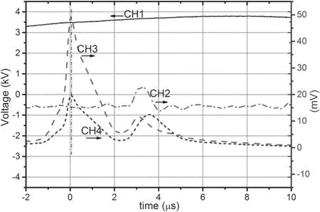
Figure 4.Applied voltage (CH1),optical emission of the jet at 5.5 mm away from the nozzle by photodiode(CH2),temporal signal by capacitive probe1 at X=5.5 mm (CH3),temporal signal by capacitive probe2 at X=20.5 mm (CH4) versus time.
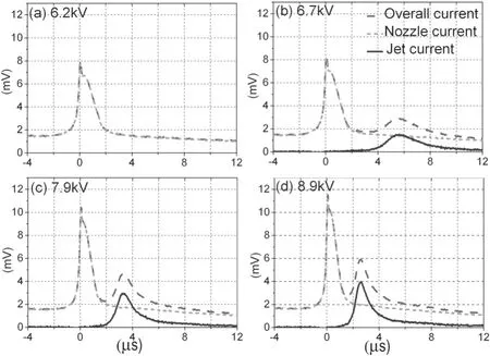
Figure 5.The waveforms of the ‘jet current pulse’ (Ijet) at different applied voltages.
In fact,the overall signal detected near the plasma jet region consists of the waveform of both Inozzleand Ijet.In contrast,when the detector is placed at the position much higher than the location (2),only the Inozzlecan be detected.As reported in [19],the space sensitivity of the probe decreases dramatically with the distance between the probe tip and space charge.In this case,the Ijetcan be neglected due to the large distance between the detector and the APPJ.Moreover,one can find a position(4)in figure 1 at which the probe2 detects the same waveform of Inozzlewith the probe1 at the location (2) (X=7 mm),as seen in figure 5.The waveform of the probe2 represents that of the Inozzleat location (2).In this way,the true waveform of Ijetat the location(2) under different applied voltages can be distinguished by subtracting the waveform of Inozzlefrom the overall current waveform.With the increase of the applied voltage,the peak value of Ijetincreases,and the pulse width decreases due to the increase of the propagation velocity of the guided ionization waves.Accordingly,the net space charges in the APPJ(Qb)increases with the applied voltage.As shown in figure 6,both the Qband mean propagation velocity of the guided ionization waves increase with the applied voltage.This is similar to the experimental and numerical results of the streamer propagation in [23,24].
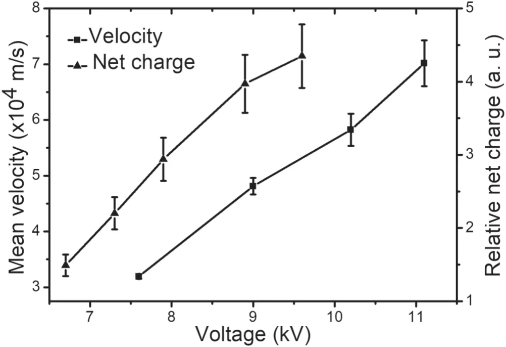
Figure 6.The mean propagation velocity between 5.5 and 20.5 mm and the net space charges at 7 mm outside the nozzle versus the applied voltages.
The streamer velocity is determined mainly by the size of the region where the electron impact multiplication is efficient.In this region,the displacement of electrons with respect to positive ions produces a high electric field,which in turn governs the electron drift motion and provides rapid ionization of molecules.The electric field is roughly determined by the Qbin the streamer head with an electrodynamic radius.With regard to the propagation of the guided ionization waves,the electric field can be expressed as

where d is the distance to the streamer head.Therefore,the propagation velocity of the guided ionization waves will increase with the Qb.
As shown from the temporal signals in figures 4 and 5,after the time t=0,the high electric field established by the Qfinitiates the avalanche-to-streamer transition in the helium channel outside the nozzle,thus the guided ionization waves launched.In other words,the floating nozzle may act as a pulsed power for the generation of the plasma jet outside of the nozzle.If the accumulated charge on this nozzle cannot initiate the transition before they flow away,or the electric field induced by the charge is not strong enough,the plasma jet cannot come out.Consequently,when the nozzle is connected to the ground directly,no plasma jet launched since the charge cannot accumulate on the nozzle.In contrast,when the nozzle is connected to the ground through a 10 MΩ resistance,the plasma jet will emerge at a higher applied voltage.In this case,the electric field to driving the guided ionization waves out can be maintained by increasing the applied voltage,since the loss of Qffrom the nozzle to the ground is very slow.
4.Conclusions
According to the above analysis based on the streamer mechanism,the physical scenario of the whole discharge process can be revealed.The positive ionization front of the DBD discharge will accumulate on the floating nozzle,which gets charged rapidly and acts as a pulsed power.The high electric field induced by the positive charge on the floating nozzle can produce a streamer discharge in the downstream region,which is the source of the guided ionization waves.
Acknowledgments
The authors would like to thank technical support from Dirk Luggenh?lscher,Qing Li,Zhenbin Wang and Peng Zen,and are very grateful to Feixiang Liu and Jiangtao Li for much help on discussion.This work is supported by National Natural Science Foundation of China (Nos.10775087 and 51907190),and the State Key Laboratory of NBC Protection for Civilian (SKLNBC 2019–16).
 Plasma Science and Technology2020年5期
- Plasma Science and Technology的其它文章
- Vickers hardness change of the Chinese low-activation ferritic/martensitic steel CLF-1 irradiated with high-energy heavy ions
- Comparison of discharge characteristics and methylene blue degradation through a direct-current excited plasma jet with air and oxygen used as working gases
- Evaluation of influence of cold atmospheric pressure argon plasma operating parameters on degradation of aqueous solution of Reactive Blue 198 (RB-198)
- Plasma-induced graft polymerization on the surface of aramid fabrics with improved omniphobicity and washing durability
- Plasma-assisted abatement of SF6 in a packed bed plasma reactor:understanding the effect of gas composition
- The far-field plasma characterization in a 600W Hall thruster plume by laser-induced fluorescence
