
Numerical solutions for cracks in an elastic half-plane
2019-11-28 08:51:14ElfakhakhreNikLongEshkuvatov
Acta Mechanica Sinica 2019年1期
N. R. F. Elfakhakhre·N. M. A. Nik Long,2·Z. K. Eshkuvatov
Abstract The behavior of the stress intensity factor at the tips of cracks subjected to uniaxial tension σ∞x = p with traction-free boundary condition in half-plane elasticity is investigated.The problem is formulated into singular integral equations with the distribution dislocation function as unknown.In the formulation,we make used of a modified complex potential.Based on the appropriate quadrature formulas together with a suitable choice of collocation points,the singular integral equations are reduced to a system of linear equations for the unknown coefficients. Numerical examples show that the values of the stress intensity factor are influenced by the distance from the cracks to the boundary of the half-plane and the configuration of the cracks.
Keywords Elastic half-plane·Multiple cracks·Singular integral equation·Sine-shaped crack
1 Introduction
The stress intensity factor(SIF)is an important quantity to describe the toughness of a material.Many researchers have put much effort into investigating the behavior of the SIF at the tips of cracks with various configurations using different approaches in either the plane [1-11] or half-plane[12-16].By applying the complex variable technique,such crack problems can be modeled using the formula
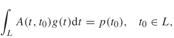
where L is the crack configuration and A(t,t0) is a kernel specified by the choice of the unknown function g(t) and the known function p(t0).If g(t)is the dislocation distribution function and p(t0) is the traction, then A(t,t0) is the Cauchy singular kernel(S1).This type of equation is widely used in half-plane crack problems.A V-notched problem was formulated and solved using the Gauss-Jacobi method by Theocaris and Ioakimidis [17]. The T-stress for multiplecrack problems was evaluated by Chen[18],and Chen and Hasebe[19]formulated the problem of multiple edge cracks and solved it using a semi-open quadrature rule.The stress concentration factors for a sinusoidal edge and periodic system of rounded V-notches in the half-plane were calculated by Savruk and Kazberuk [20], while Ioakimidis and Theocaris[21]proposed S1 for an arbitrary system of curvilinear cracks in the half-plane or two bonded half-planes,and solved the problem numerically using the Lobatto-Chebyshev method for a circular arc and straight oblique edge cracks in the half-plane. Also, the problem of curvilinear cracks in an isotropic half-plane into which a rigid punch is pressed was investigated and solved numerically using the mechanical quadrature method[22,23].S1 was also applied to analyze the problem of multiple curved cracks in a functionally graded orthotropic half-plane[24].A Cauchy singular equation(S2)was formulated for the plane elasticity [25-27], where g(t) is the crack opening displacement(COD)and p(t0)is the resultant force.
The kernel is weakly singular(S3)if g(t)is the dislocation distribution function and p(t0)is the resultant force.The weakly singular integral equation for crack problems in plane elasticity was formulated by Cheung and Chen[28],as well as for an isotropic half-plane with a curved crack[29].If g(t)is COD and p(t0)is the traction,the kernel is hypersingular.An integral equation with a hypersingular kernel was proposed by Chen et al. [30] for curved crack problems in the half-plane. A complex hypersingular integral equation was developed for the elastic half-plane with holes,notches,and cracks of arbitrary shape[30,31].
In addition, Kratochvil and Becker [33] utilized the complex variable method to investigate the stresses in an isotropic half-plane weakened by a finite number of holes,and solved the problem using the method of compound asymptotic expansions.The problem of an edge curvilinear crack in an elastic half-plane was formulated by Datsyshin andMarchenko[34].Furthermore,thedistributeddislocation technique was proposed to construct an integral equation for a half-plane containing multiple edges[35],as well as curved cracks[36].The distributed dislocation dipole technique was developed to analyze multiple straight,kinked,and branched cracks in an elastic half-plane[37].
In this paper,we extend the work in Ref.[38]to the more complicated crack configurations,i.e.,multiple inclined,circular arc, and sine-shaped cracks in half-plane elasticity with traction-free boundary condition.The problem is solved numerically by using the curve length coordinate method to map the crack configuration onto the real axis. The Gauss quadratureruleisthenappliedtoreducethesystemofintegral equations to a system of linear equations.Several numerical examples considering different cases of crack configurations and arrangements are presented. The interactions between the cracks are investigated and displayed graphically.
2 Mathematical formulation
Let Φ(z)=φ′(z)and Ψ(z)=ψ′(z)be two complex potentials, then the stresses (σx, σy, σxy), the resultant forces(X,Y),and the displacements(u,v)can be described as[39]
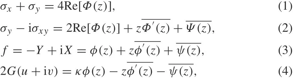
where G is the shear modulus of elasticity,κ =(3-v)/(1+v)in the plane stress problem,κ =3-4v in the plane strain problem, v is the Poisson's ratio, and a bar over a function denotes its conjugated value. The derivative in a specified direction(DISD)is defined as
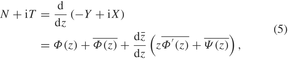
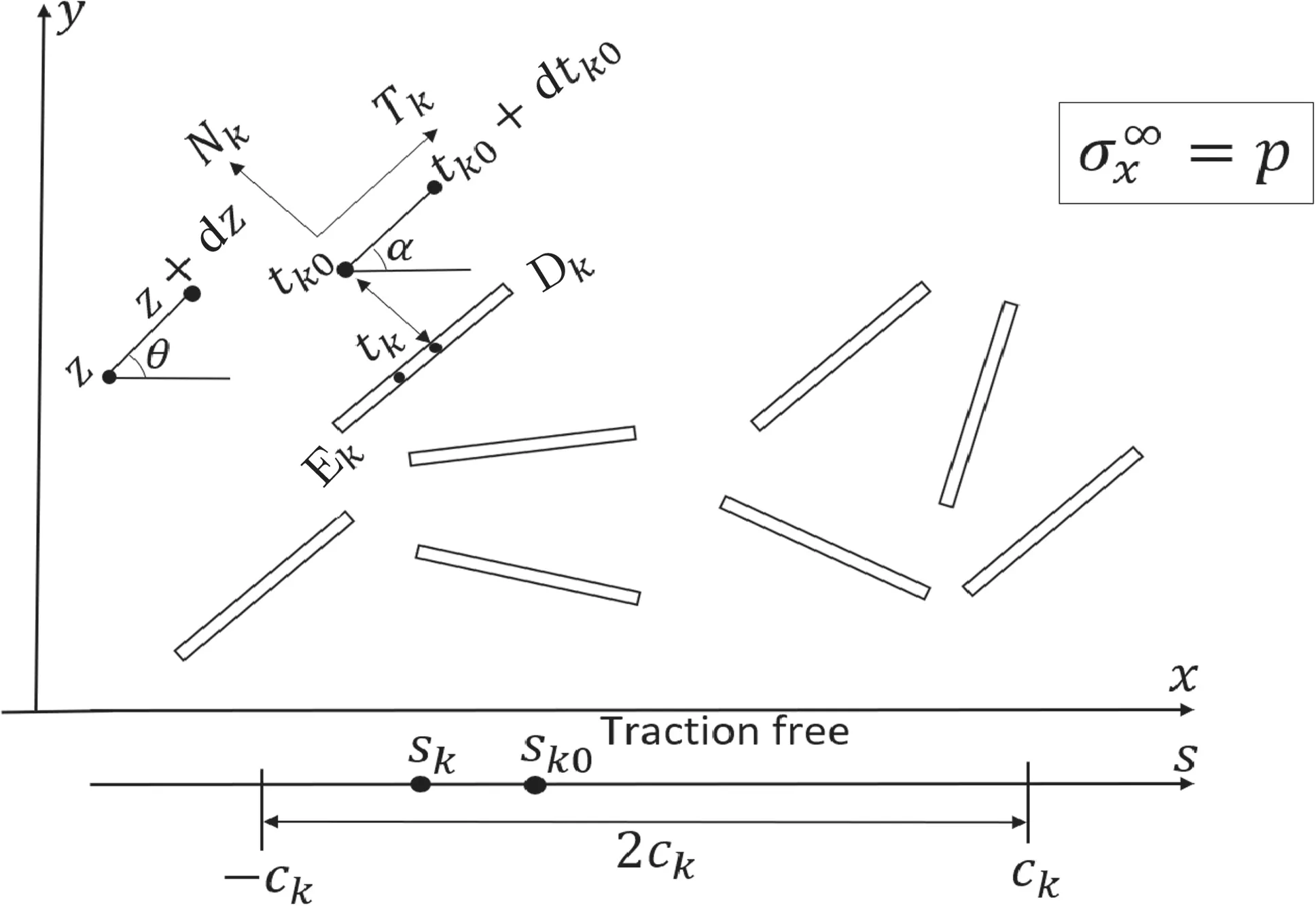
Fig.1 Multiple cracks in an elastic half-plane with traction-free boundary condition
where N +iT denotes the normal and tangential tractions along the crack segment(Fig. 1). The value of N +iT depends on the position of the point z as well as the direction of the segment dˉz/dz[40].
Now consider n cracks lying in the upper half-plane under uniaxial tension σx= p with traction-free boundary, as shown in Fig. 1. In Fig. 2, the crack problem in Fig. 2a is a superposition of the two particular problems shown in Fig. 2b, c. For the problem in Fig. 2c, some tractions are applied on the crack face.Then,Fig.2c is decomposed into Fig. 2d, e. In Fig. 2d, the dislocation distribution function g′(t)is assumed along the prospective crack location,which lies in an infinite plate. The complex potentials is denoted by Φp(z) and Ψp(z). Figure 2e illustrates a regular stress field which compensates the tractions on the boundary of the half-plane(Lb)caused only by the stress field in Fig.2d.The complex potentials are related to a regular stress field (2e)denoted by Φc(z)and Ψc(z)([30]).
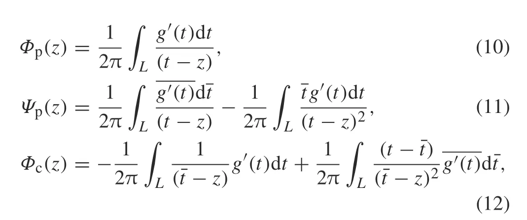
The complex potentials for each crack can be expressed as

where z = x+iy and the subscripts“p”and“c”indicate the principal and complementary parts of Φ(z),Ψ(z), respectively. The complex potentials shown in Eq. (6) are called the modified complex potentials[40].
Since, along the boundary of the half-plane, or Lb, we have z = ˉz,and dz = dˉz,the traction-free condition along the boundary of the half-plane,or Lb,is as follows:
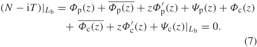
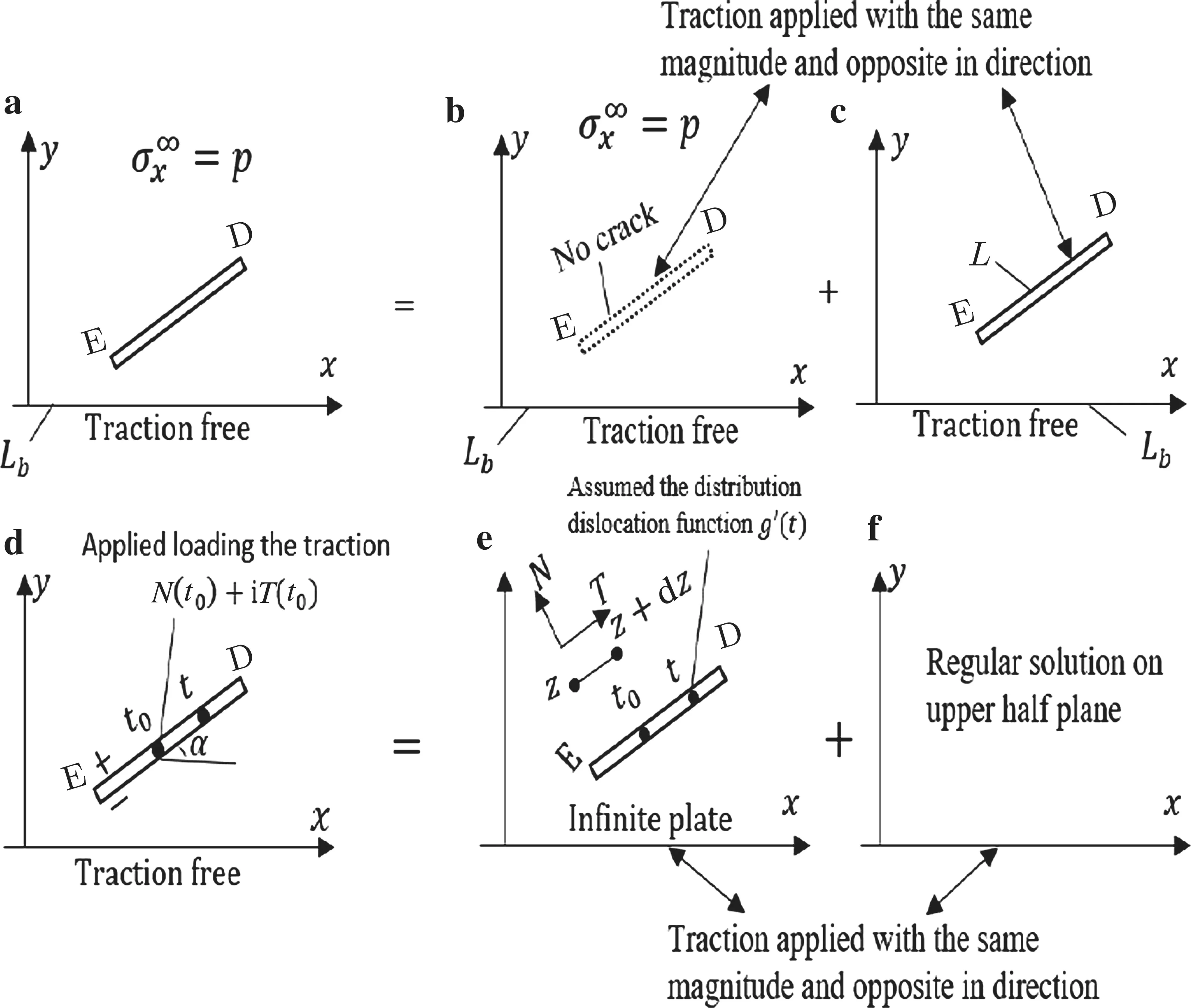
Fig.2 Formulation of the crack problem in the upper half-plane with traction-free boundary: a original problem with remote tension = p,b an elastic half-plane with remote tension = p,c a crack with traction applied on its face,d a crack in an infinite plate modeled by a dislocation distribution that can be described by the complex potentials Φp and Ψp,and e regular solution for the upper half-plane that can be described by the complex potentials Φc and Ψc
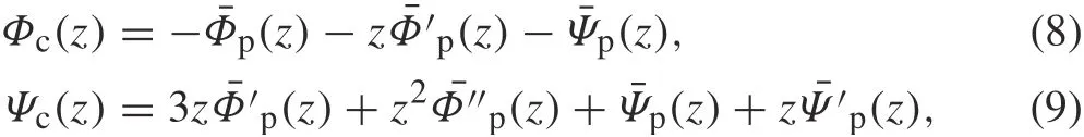
It is assumed that the complex potentials Φp(z)and Ψp(z)are obtained from the original complex potentials in an infinite plate.From Eq.(7),we will obtain the complementary part of the complex potentials Φc(z)and Ψc(z)as follows:
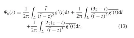
where the undetermined dislocation distribution function on each crack face g′(t)is defined as
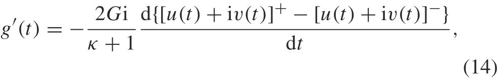
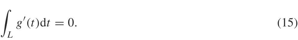
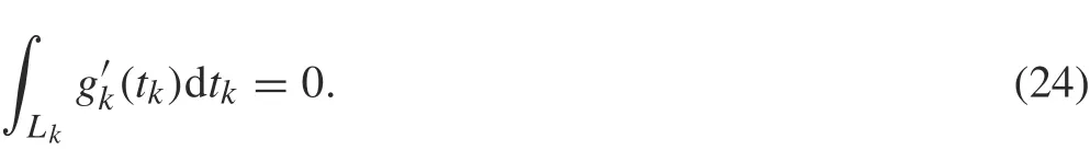
where t ∈L,the subscript“+”(or“-”)means the upper(or lower)faceofeachcrack,and[u(t)+iv(t)]+-[u(t)+iv(t)]-represents the displacements at a point t of the upper and lower faces of each crack L. In Eq. (14) the expression d{}/dt should be defined as in Ref. [40]. The singlevaluedness condition is
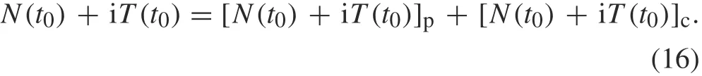
One can also write the traction N+iT in terms of its principal and complementary parts as
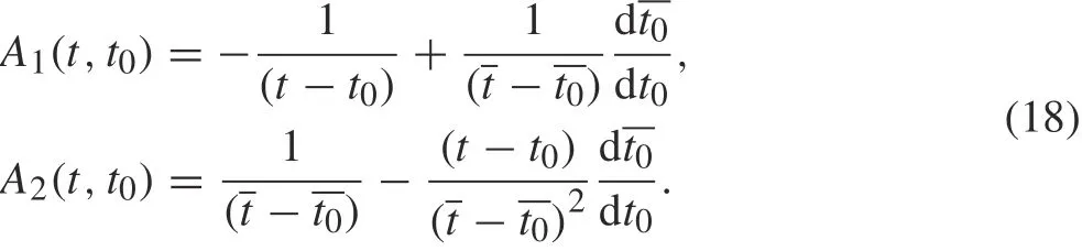
By substituting Eqs. (10) and (11) into Eq. (5), and letting the point z approachand ddz to dand using the generalized Sokhotski-Plemelj formula for Cauchy-type integrals[39],we obtain

where t0∈L, and the first integral on the left-hand side is singular and the remainders are regular,and the kernels are expressed as
Similarly, substituting Eqs. (12) and (13) into Eq. (5), we obtain
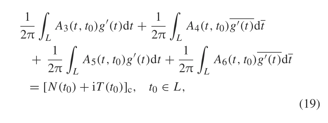
where all integrals on the left-hand side are regular,and the kernels are expressed as

The singular integral equation for each crack is obtained by substituting Eqs.(17)and(19)into Eq.(16),which gives
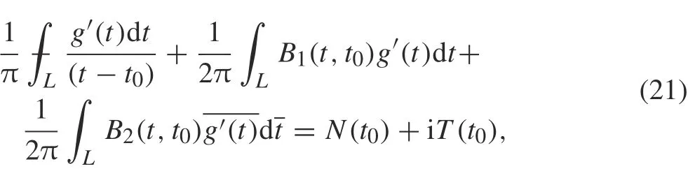
where t0∈L,and
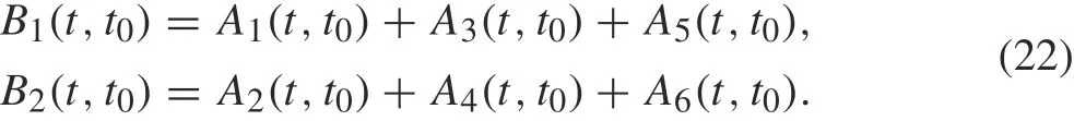
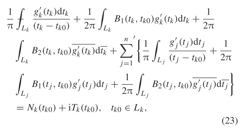
For n cracks, let Nk(tk0)+iTk(tk0) represent the tractions applied at point tk0of crack k for k =1,2,...,n composed of n parts to obtain the following system of singular integral equations:
3 Solution strategy
In solving Eq. (23) subject to Eq. (24), we map the cracks onto a real axis by skwith intervals of 2ckfor crack k,k =1,2,...,n.The mappings are expressed as[41,42]
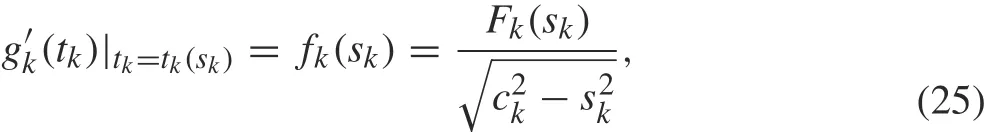
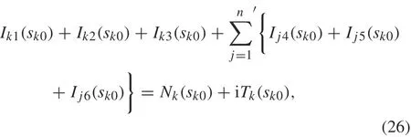
whereFk(sk)= Fk1(sk)+iFk2(sk).Using this transformation,all integrals in Eqs.(23)and(24)will be transformed into integrals on the real axis s.Substituting Eq.(25)into Eqs.(23)and(24),respectively,yields
where
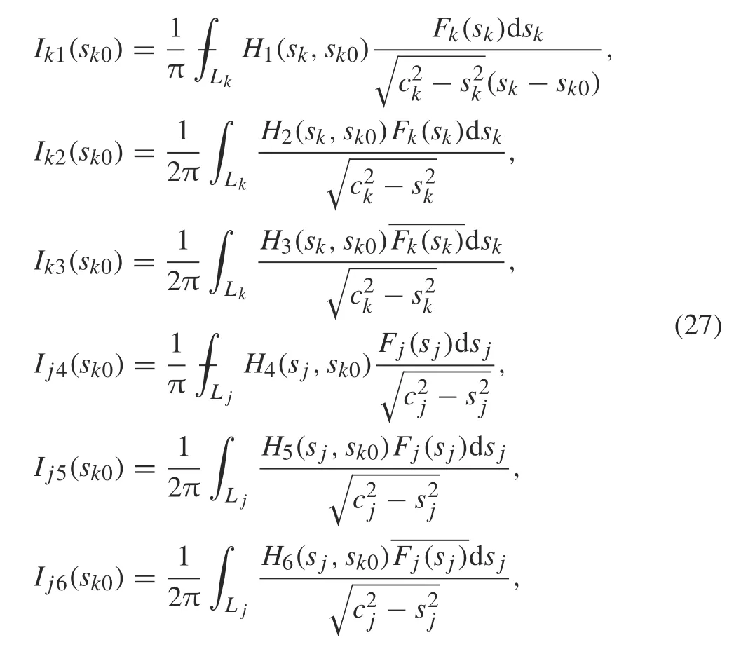
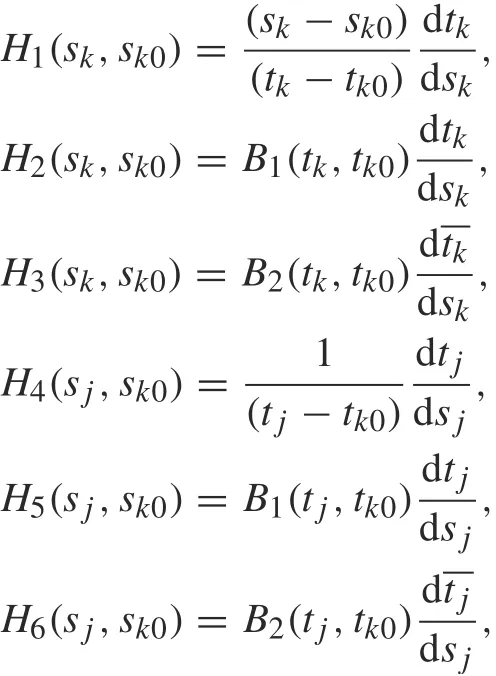
for k, j = 1,2,...,n where j /= k, and H1, H2, H3, H4,H5,and H6are,respectively,defined by
and
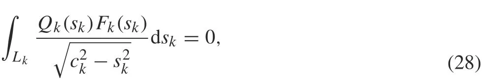
where Qk(sk)=dtk/dskfor k, j =1,2,...,n.
The following Gauss integration rules[43]are also used in solving integral equations
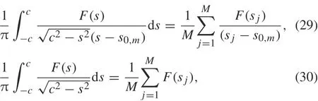
where M is some integer,and

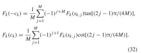
The values Fk(ck) for k = 1,2,...,n are calculated by extrapolation formulae[40]as follows:
4 Numerical examples
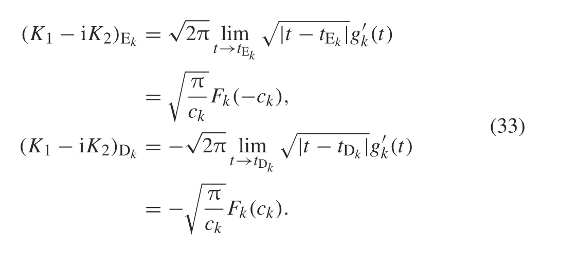
To verify the accuracy of the method used in this work,several examples are presented.The SIF at the crack tips Ekand Dkof crack k for k =1,2,...,n are defined as
4.1 Example 1
4.1.1 Example 1.1
Consider an arc crack with radius R and spanning angle 2δ = π/6 that lies in the upper half-plane with tractionfree boundary,subjected to remote tension σ∞x= p(Fig.3).
The SIFs are expressed as
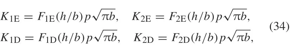
where b= R sin δ.
Figure 4 illustrates the nondimensional SIFs at crack tips E and D for h/b = 0.2,0.4,...,2 where b = R sin(δ)and h is the distance between tip D of the crack and the boundary of the half-plane.Our results are in good agreement with those of Chen et al.[30].
4.1.2 Example 1.2
As reported in Ref. [40], the principal part of the modified complex potential in Eq. (17) is equivalent to the original complex potential for the curved crack in an infinite plane.
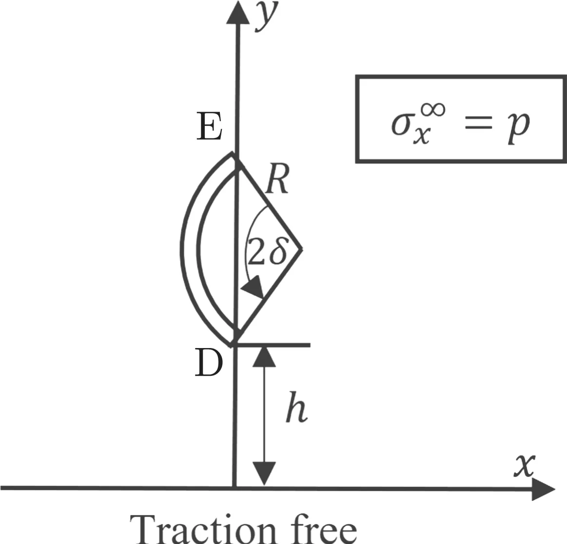
Fig.3 An arc crack in an elastic half-plane
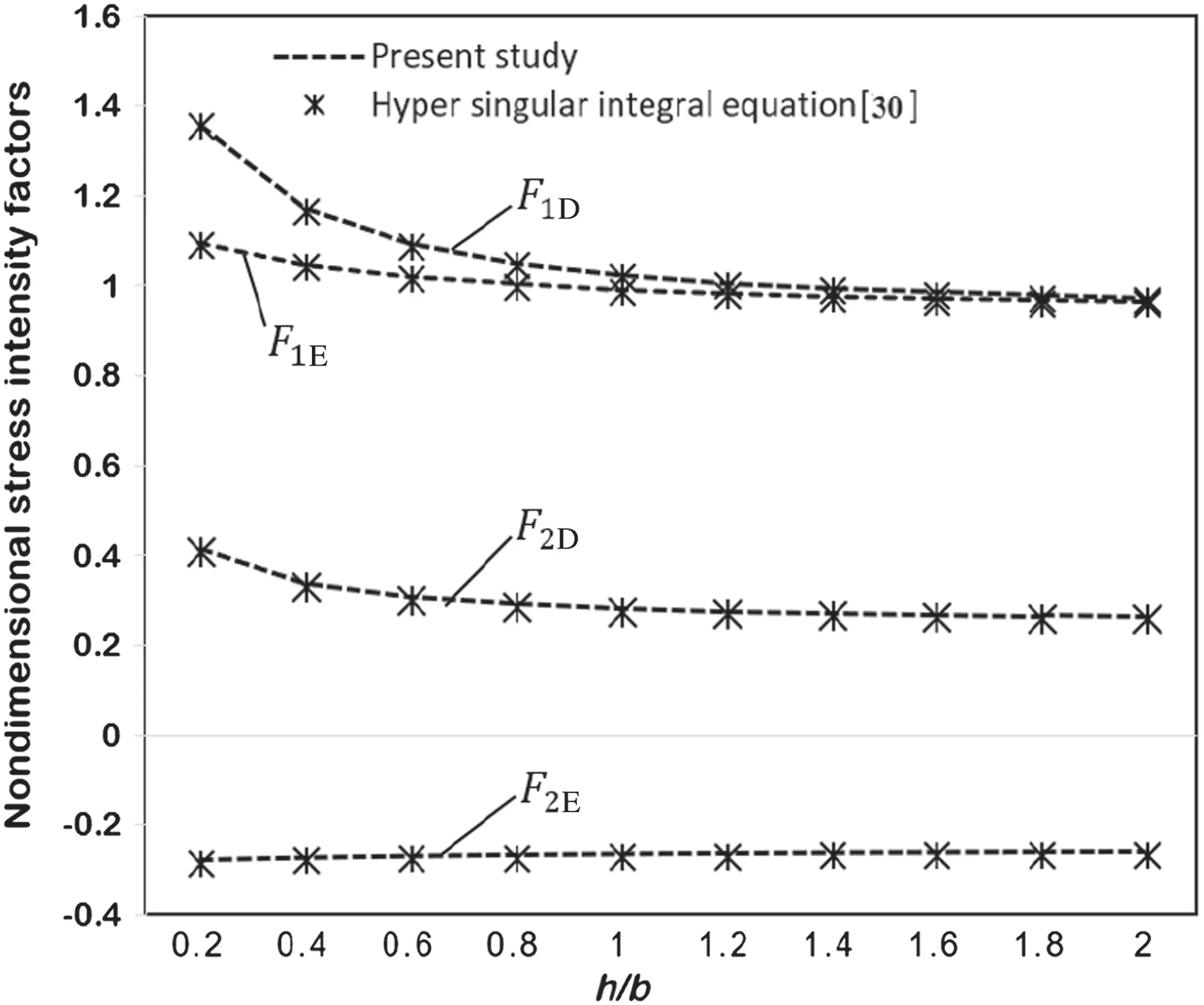
Fig.4 Nondimensional SIF for an arc crack in an elastic half-plane as in Fig.3
Let the crack configuration be defined as
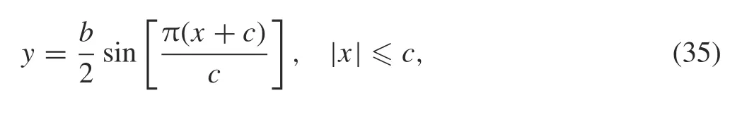
where b/2 and 2c are the amplitude and the distance between the crack tips E and D, respectively. The crack lies in an infinite plane as shown in Fig.5a with b/c = 1,2,4 under uniaxial tension σ= p.
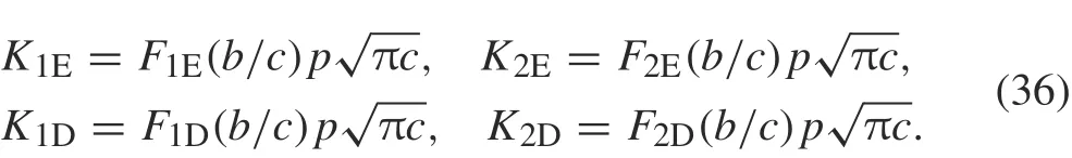
Figure 5b shows the crack lying in the upper half-plane under uniaxial tension= p.The SIFs at the crack tips E and D are expressed by

Fig.5 a A sine-shaped crack in an infinite plane.b A sine-shaped crack in an elastic half-plane with traction-free boundary
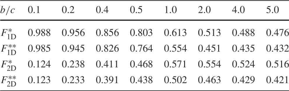
Table 1 Nondimensional SIFs for a sine-shaped crack in an infinite plane(Fig.5a)
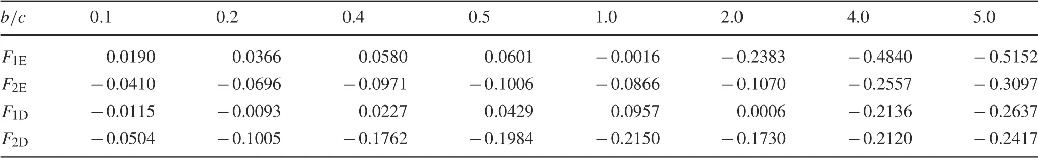
Table 2 Nondimensional SIFs for a sine-shaped crack in a half-plane(Fig.5b)
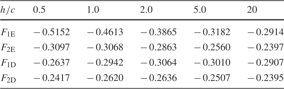
Table 3 Nondimensional SIFs for a sine-shaped crack in a half-plane(Fig.5b)as h/c changes for b/c=5.0
The SIFs are calculated for 0.1 ≤b/c ≤5. Table 1 presents the values of the SIF at crack tip D of the sine-shaped crack in an infinite plane.They are in good agreement with those of Chen[26].The SIFs at crack tips E and D are equal.For a sine-shaped crack in a half-plane,the results are listed in Table 2 for h/c = 0.5, where h is defined as in Fig. 5b.The closer the crack to the boundary of the half-plane, the higher the negative value of the SIF,as shown in Table 3.
4.2 Example 2
4.2.1 Example 2.1
Assume that two sine-shaped cracks with the same length 2c lie in the upper half-plane under uniaxial tension= p
with traction-free boundary (Fig. 6). The SIFs can be expressed as
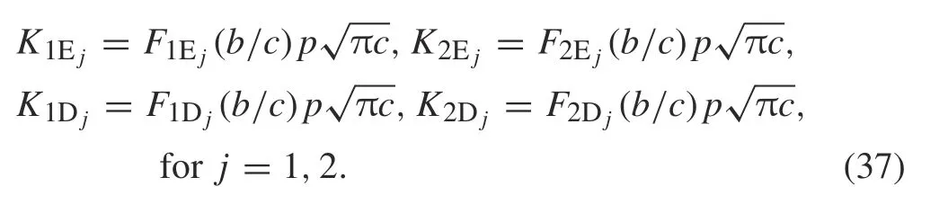
For two sine-shaped cracks in series as in Fig.6a,which can be expressed as in Eq. (35), Fig. 7 displays the SIFs against b/c for h/c = 0.1,0.5,1.0, where h is defined as in Fig.6.Note that a significant impact on the SIF at cracks tips E1, E2, D1, and D2appears when the cracks are close to the boundary (h/c = 0.1). The value of F1at crack tips D1and D2increases as h/c increases for 0.5 <b/c <1.0.Figure 8 shows the SIFs at crack tips E1and D1against b/c for h/c = 0.1,0.5,1.0 for the cracks in Fig. 6b. We found that F1E1= F1D2,F2E1= -F2D2,F1D1= F1E2,and F2D1=-F2E2.There is a significant impact at crack tips E1and D1.
Figure 6c shows two sine-shaped cracks in parallel position.The nondimensional SIFs against λ/c for b/c=1,3,5 and h/c = 0.5 are displayed in Fig.9.The SIFs increase as the amplitude of the cracks increases,except at crack tip D1.Also,F1increases at cracks tips E1and D2as λ/c increases,with a slight effect at E2and D1.
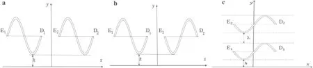
Fig.6 Two sine-shaped cracks in an elastic half-plane in different positions:a in series,b in opposite position,and c parallel
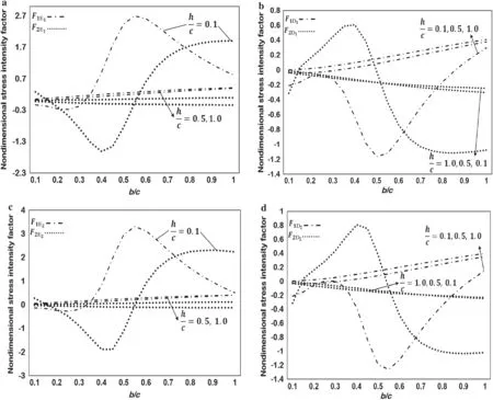
Fig.7 Nondimensional SIF for two sine-shaped cracks as in Fig.6a at crack tip a E1,b D1,c E2,and d D2
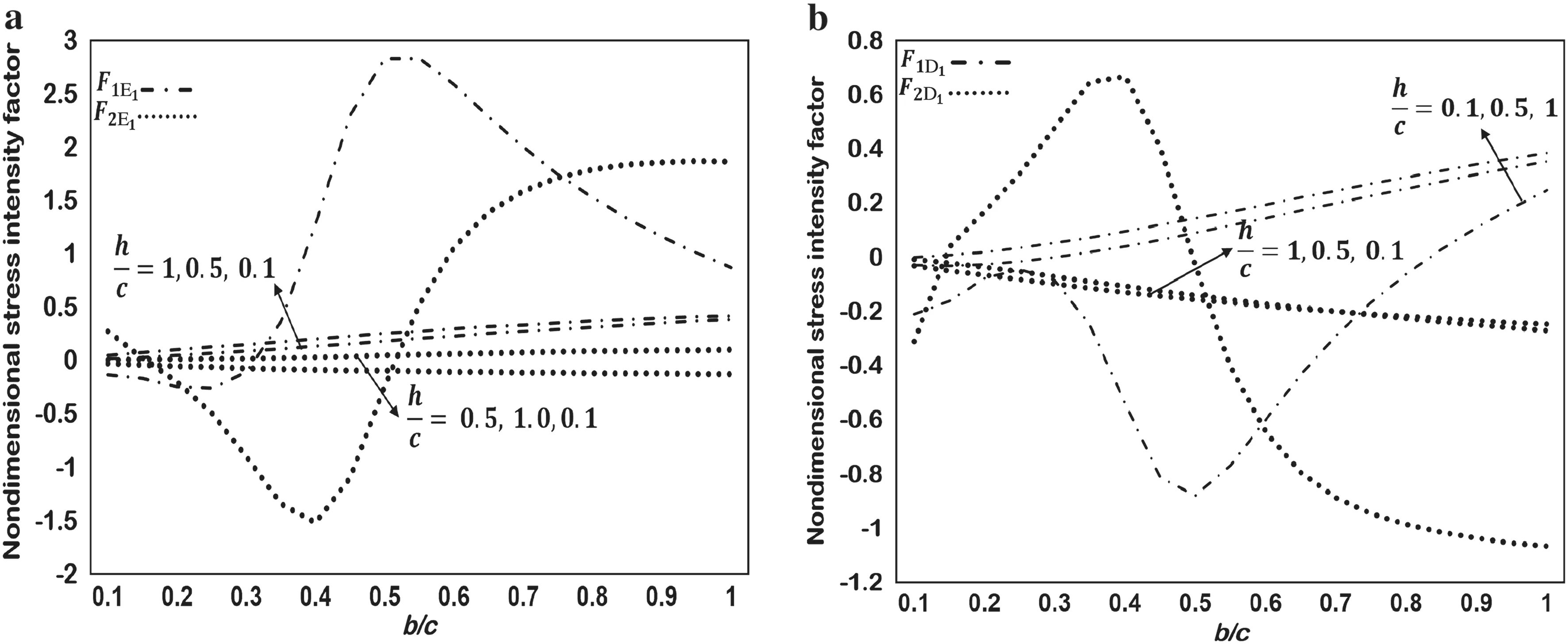
Fig.8 Nondimensional SIF for two sine-shaped cracks as in Fig.6b at crack tip a E1 and b crack tip D1
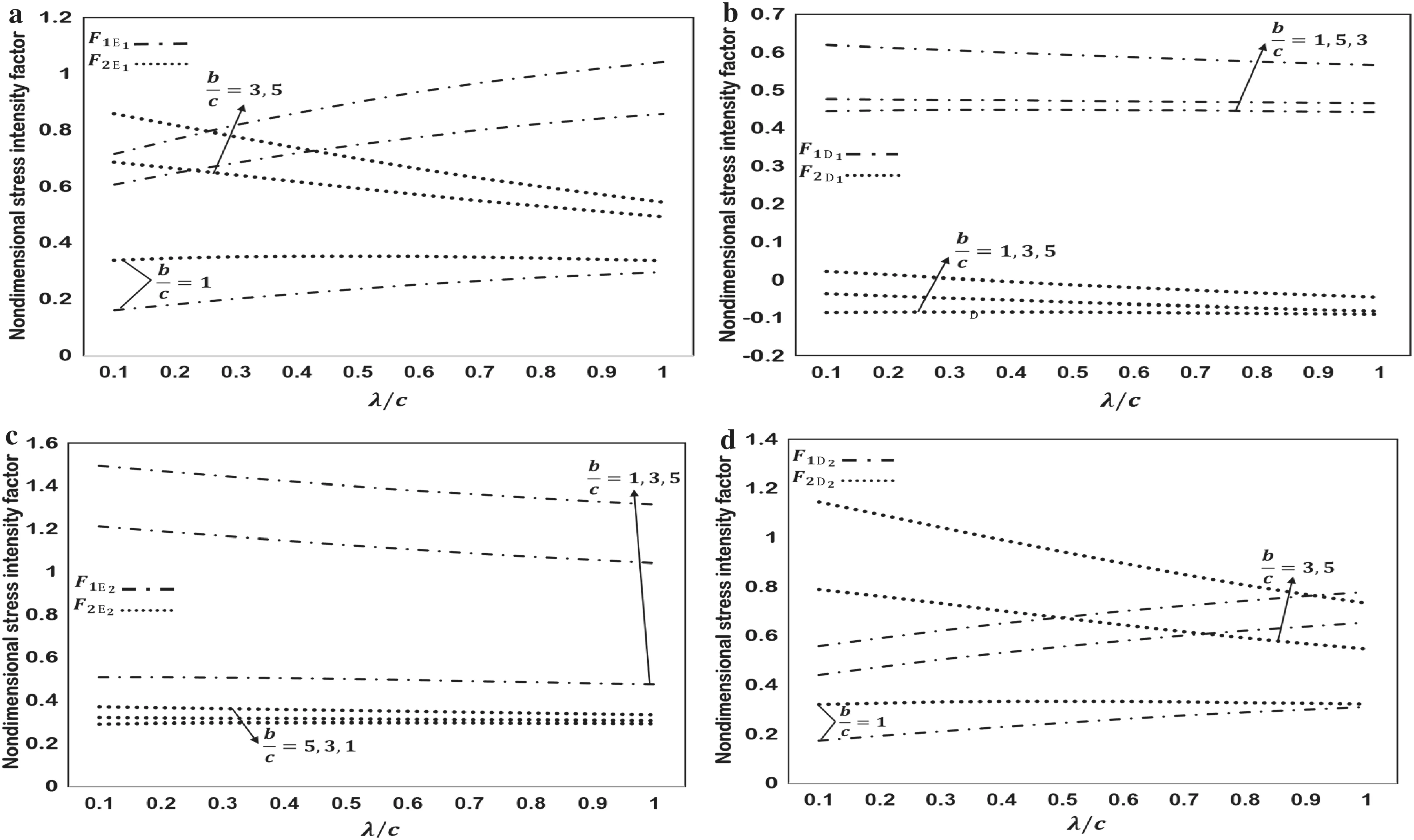
Fig.9 Nondimensional SIF for two parallel sine-shaped cracks as in Fig.6c at crack tip a E1,b D1,c E2,and d D2
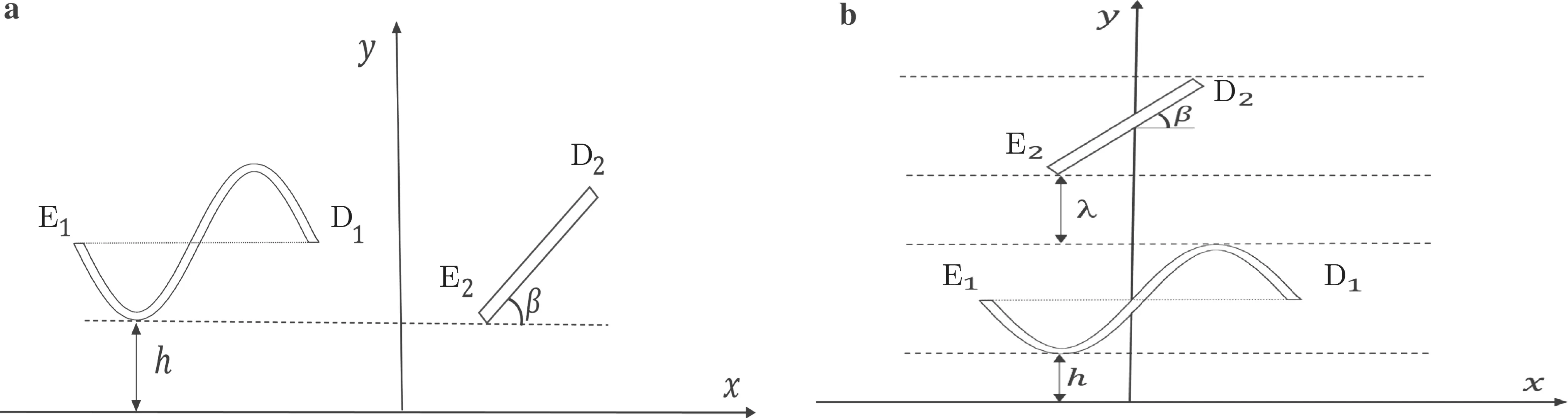
Fig.10 A sine-shaped and an inclined crack in an elastic half-plane with different positions:a sine-shaped crack on the left of an inclined crack,and b an inclined crack on top of a sine-shaped crack
4.2.2 Example 2.2
Consider an inclined crack of length 2a and a sine-shaped crack lying in the upper half-plane subjected to= p,as in Fig.10.The SIFs are expressed as follows:


For the cracks in Fig.10a,the nondimensional SIFs against h/c for β = 10°,45°,90°, and b/c = 2.0 are displayed in Fig.11.It can be seen that F1E1decreases as the angle of inclination β increases,but increases as the crack approaches the boundary. F1D1increases as the angle of inclination of the crack β increases,but decreases as the crack approaches the boundary. The values of F1E2and F1D2increase as β increases or the cracks approach the boundary when β =45°,90°.
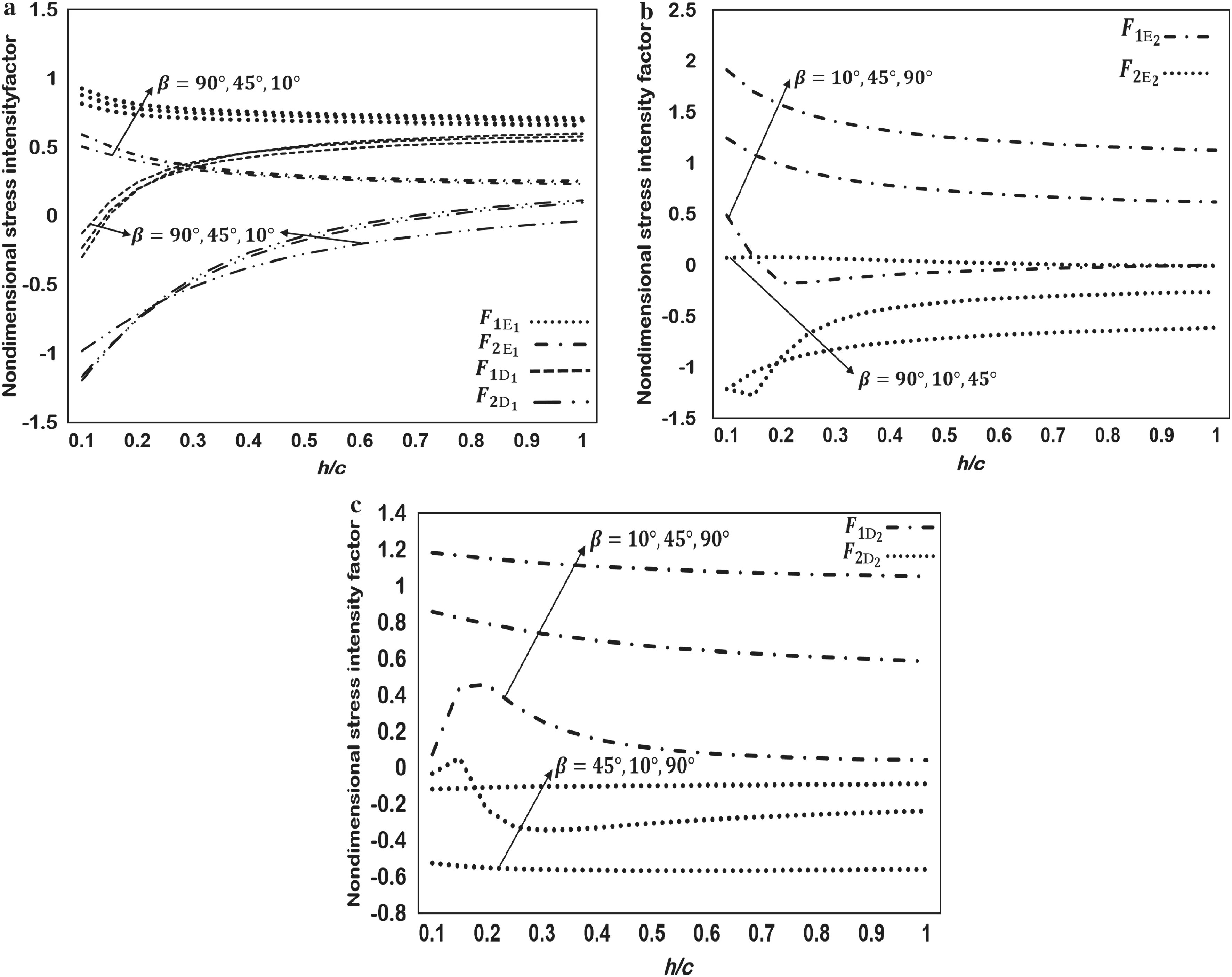
Fig.11 Nondimensional SIF for the sine-shaped and inclined cracks as in Fig.10a at a tips of the sine-shaped crack,b crack tip E2,and c crack tip D2
Fig.12 Nondimensional SIF for a sine-shaped and an inclined crack as in Fig.10b:a as β changes for λ/c=0.1,b as λ/c changes for β =90°
If the crack positions are as in Fig. 10b, the nondimensional SIFs versus β and λ/c are displayed graphically in Fig.12. F1D2and F1E2increase as β increases,whereas the SIFs are only slightly affected by change of λ/c.
4.2.3 Example 2.3
Consider a circular arc and a sine-shaped crack in the upper half-plane subjected to uniaxial tension σ∞x= p, as in Fig.13.The radius of the circular arc crack is R.The SIFs can be expressed as
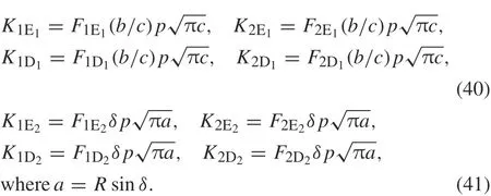
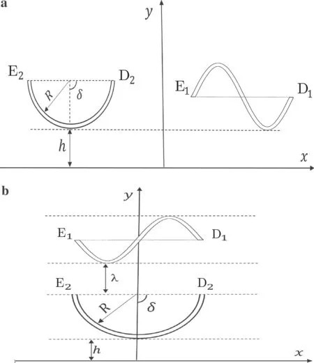
Fig.13 Different positions of a sine-shaped and a circular arc crack in an elastic half-plane:a a sine-shaped crack on the right of a circular arc crack,and b a sine-shaped crack above a circular arc crack
For the cracks placed as in Fig.13a,the nondimensional SIFs against δ with h/c =0.1 and b/c =1,2,3 are plotted in Fig. 14. As b/c increases, the value of F1E1decreases while F1D1increases.F1E2and F1D2increase as δ increases.
Figure 15 shows the SIFs versus δ for b/c = 0.5,h/c = 0.1, and λ/c = 0.1,0.5,1.0 for the crack configuration shown in Fig. 13b. Note that, if the cracks approach each other, then F1E1increases while F1D1decreases. The SIFs at crack tips E1,E2,and D2increase as δ increases.
Fig.14 Nondimensional SIFs for a sine-shaped and a circular arc crack as in Fig.13a at a crack tip E1,b crack tip D1,and c at the tips of the circular arc crack

Fig.15 Nondimensional SIFs for a sine-shaped and a circular arc crack as in Fig.13b at a crack tip E1,b crack tip D1,and c at the tips of the circular arc crack
Fig.16 Three straight cracks subjected to normal stress(σy = p)in an infinite plane
4.3 Example 3
Consider three cracks placed in the upper half-plane under uniaxial tension σ∞x= p. The nondimensional SIFs are expressed as in Eq. (33) where k = 1,2,3. The following examples present the SIFs for some different positions of the cracks.
Fig. 17 A straight and two inclined cracks subjected to shear stress(σx = p)in an elastic half-plane
Fig. 18 Nondimensional SIFs for a straight and two inclined cracks in a half-plane (see Fig. 17) as β is changed for a 2c/λ = 0.1 and b 2c/λ=0.1,0.5,0.9
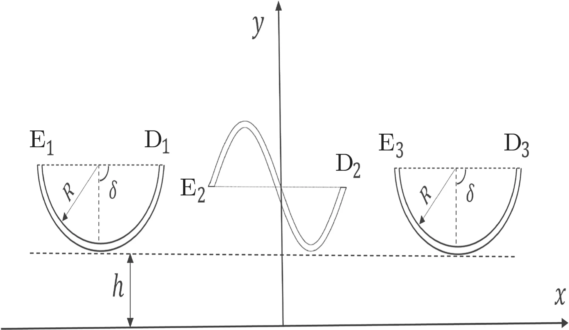
Fig.19 A sine-shaped and two circular arc cracks in an elastic halfplane
4.3.1 Example 3.1
Toconfirmtheaccuracyofourmethod,wefirstconsiderthree straight cracks lying in an infinite plane subjected to σ∞y= p as in Fig.16.The SIFs are computed using Eq.(33),and the results are presented in Table 4,revealing that our numerical results agree with those of Lam and Phua[41],and the exact solution by Sih[42].
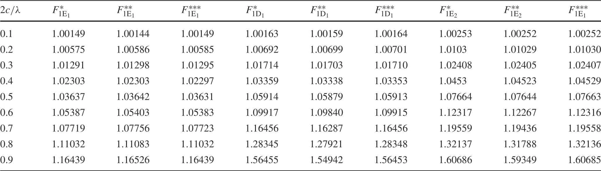
Table 4 Nondimensional SIFs for three straight cracks in an infinite plane
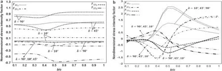
Fig.20 Nondimensional SIFs for a sine-shaped and two circular arc cracks(Fig.19)at crack tips a E1 and D1,and b E2 and D2
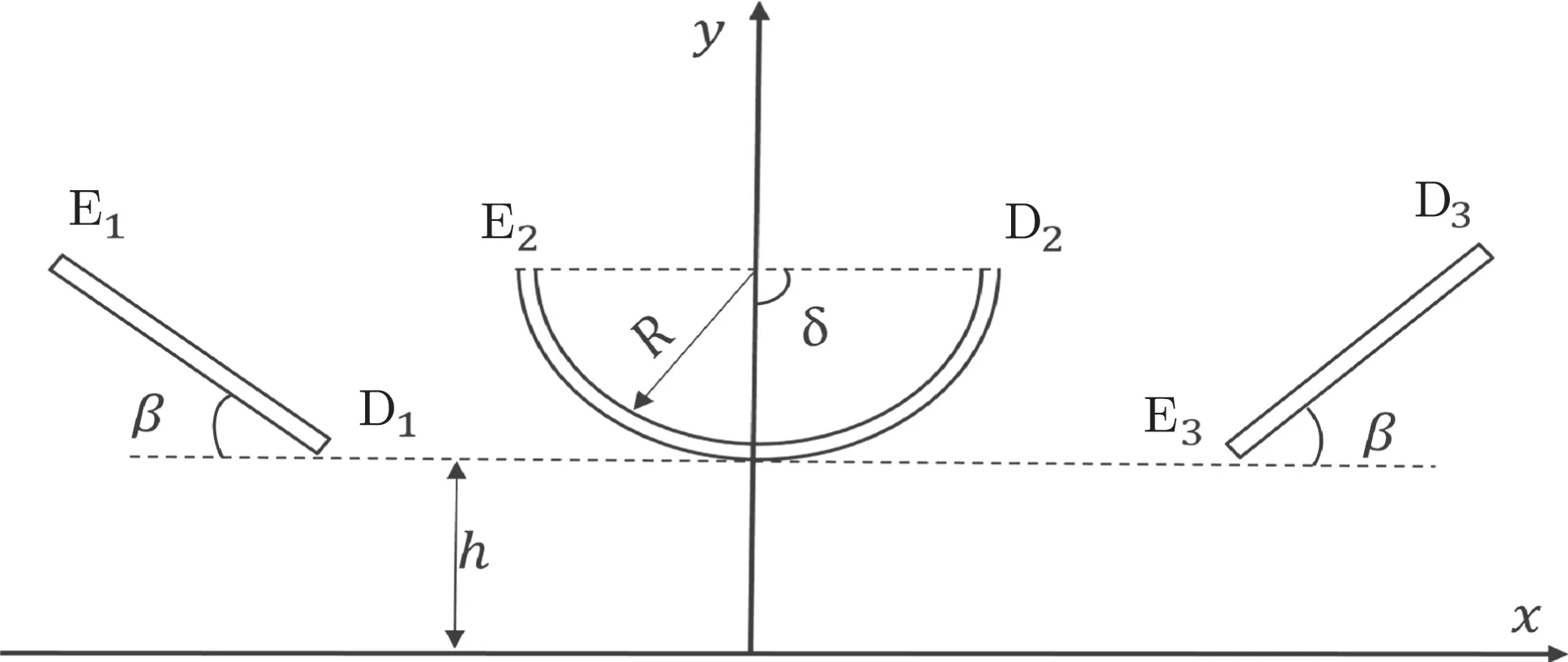
Fig.21 Two inclined cracks and a circular arc crack in an elastic halfplane
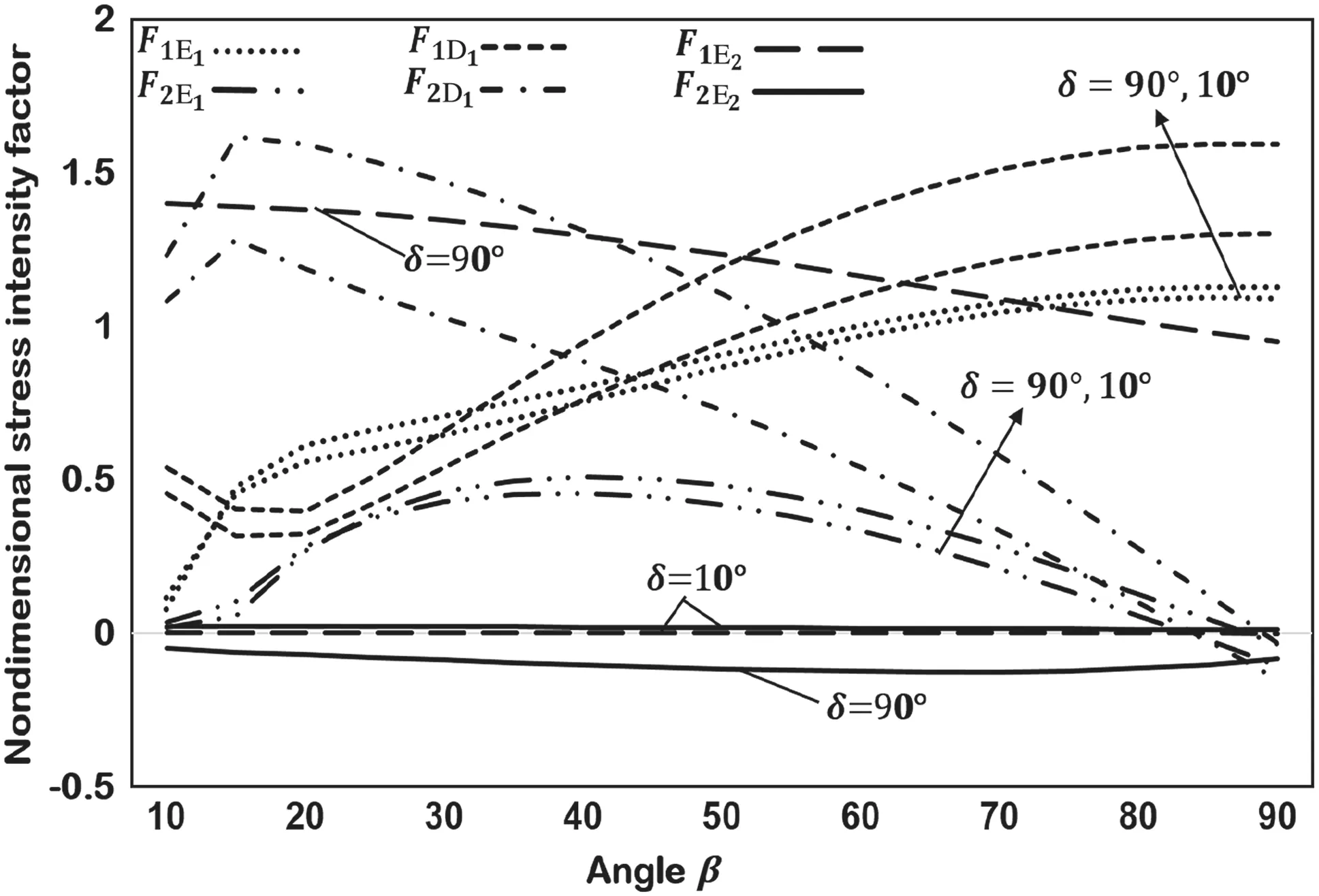
Fig. 22 SIFs for two inclined cracks and a circular arc crack in an elastic half-plane(Fig.21)
Now consider two inclined cracks and a straight crack lying in the upper half-plane under uniaxial tension σ∞x= p(see Fig.17).The SIFs are displayed graphically in Fig.18a for 2c/λ=0.1,h/c=0.5.Figure 18b shows F1for 2c/λ=0.1,0.5,0.9.Note that less impact is detected at the tips of the straight crack, and the real parts of the SIFs at the left and right crack tips are equal while the imaginary parts are of opposite sign.The SIFs for the inclined cracks increase as β increases,and F1D1>F1E1when 50°≤β ≤90°.Also,F1E1and F1D1increase as 2c/λ decreases.
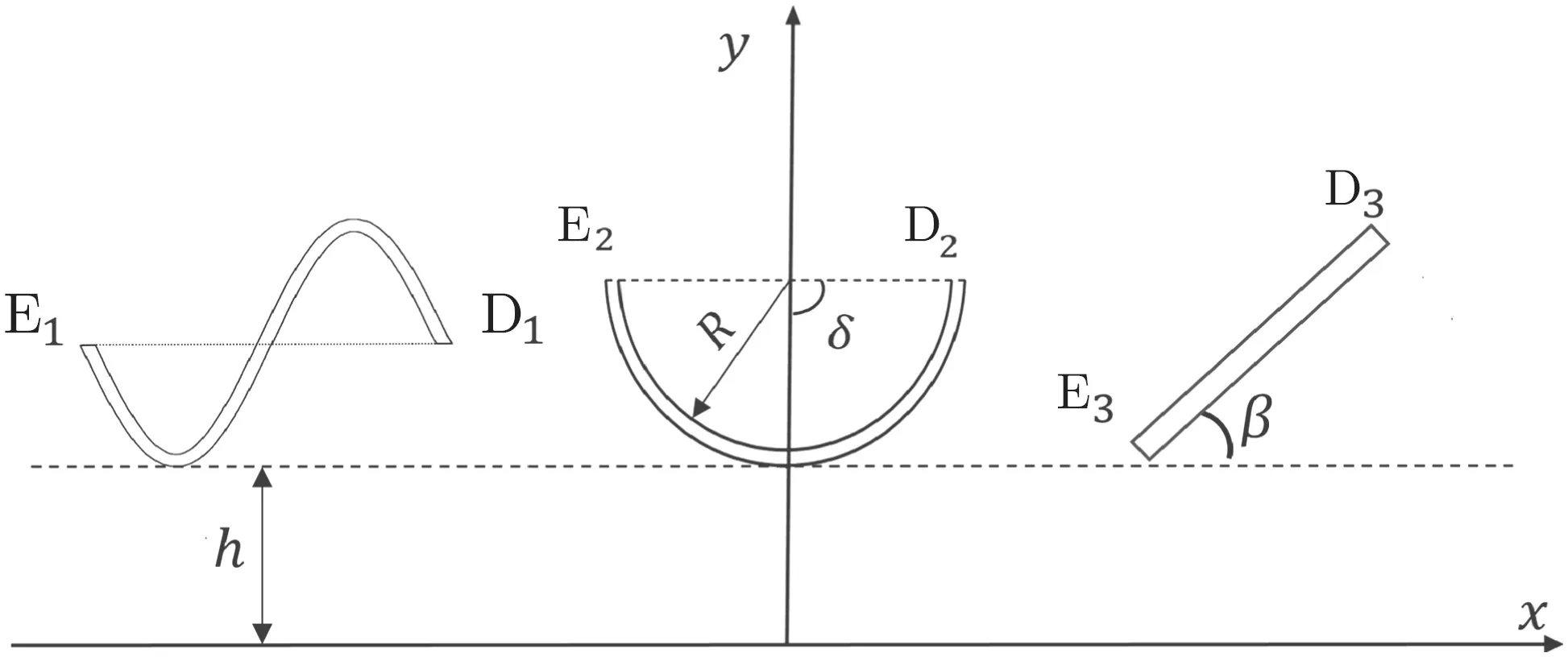
Fig.23 A sine-shaped crack,a circular arc crack,and an inclined crack in an elastic half-plane
4.3.2 Example 3.2
Figure 19 shows a sine-shaped and two circular arc cracks in the upper half-plane subjected to σ∞x= p.The SIFs are plotted in Fig.20 for h/c=0.1.It is observed that the values of F1E1and F1D1increase as δ increases,and F1E2>F1D2for b/c >0.3.
4.3.3 Example 3.3
Figure 21 shows two inclined cracks and a circular arc crack placed in the upper half-plane with h/c = 0.1. Figure 22 shows the SIF against the angle β for δ =10°,90°.F1E1and F1D1increase as β increases,but decrease as δ increases.
4.3.4 Example 3.4
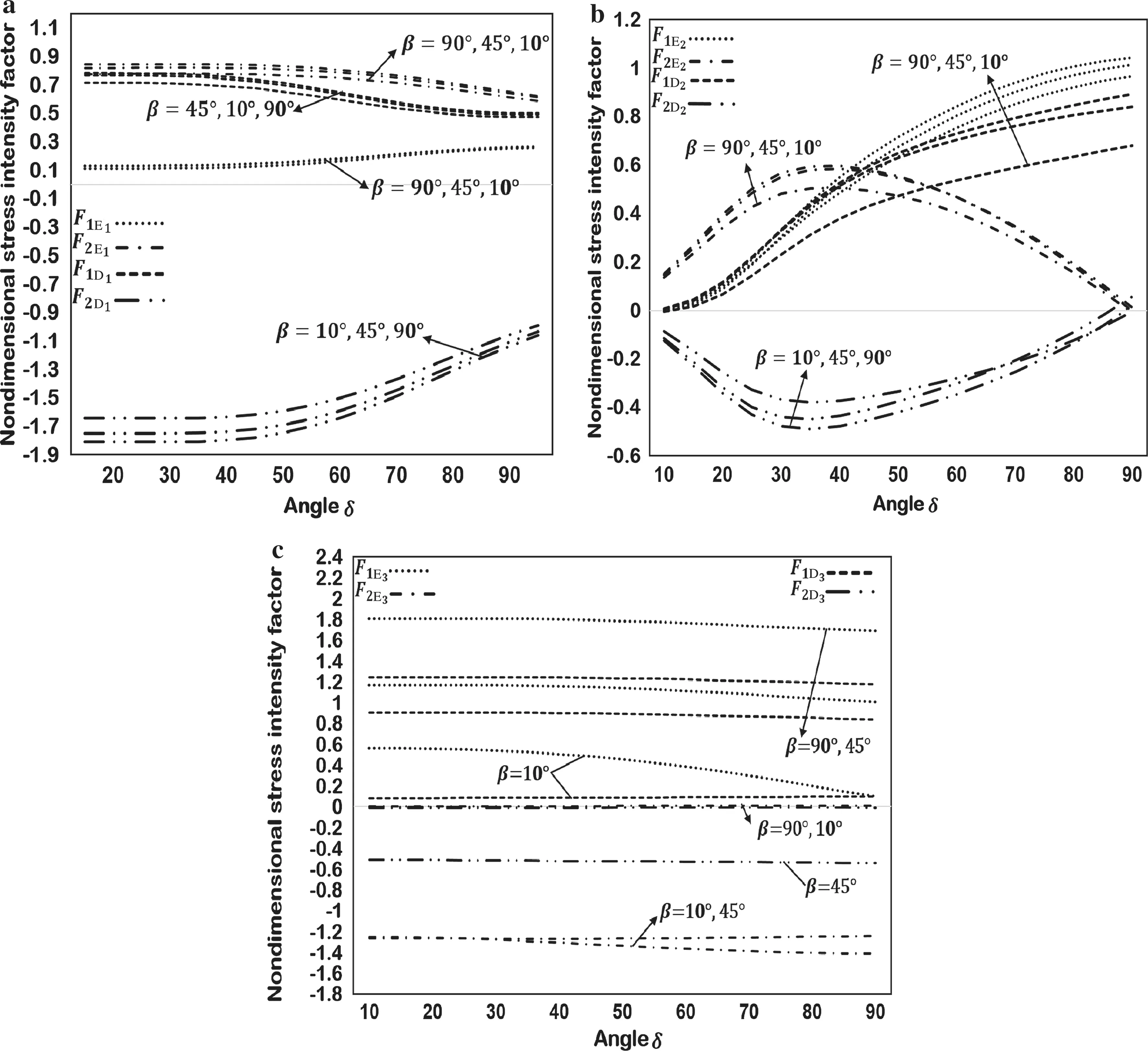
Fig.24 SIFs for a sine-shaped crack,a circular arc crack,and an inclined crack in an elastic half-plane(see Fig.23)at the tips of the a sine-shaped crack,b circular arc crack,and c inclined crack
Figure 23 shows a sine-shaped,a circular arc,and an inclined crack. In the computation, we chose h/c = 0.1, β =10°,45°,90°, and b/R = 2. Figure 24 shows that, as δ increases,F1E1increases while F1D1decreases,with a slight effect with increase of β.The SIFs at E2and D2increase with increment of δ but decrease with increment of β.However,increment of β causes an increment of the SIFs at E3and D3.Also observe the stronger effect on the inclined crack at tip E3,since it is closer to the boundary.
5 Conclusions
The problem of multiple cracks in an isotropic half-plane was studied. A singular integral equation for multiple cracks is formulated and solved numerically.Numerical results show that the SIFs are greatly influenced by the amplitude of the sine-shaped crack, the configuration of the cracks, and the distance from the cracks to the boundary of the half-plane.
AcknowledgementsThe author would like to thank University Putra Malaysia for Putra Grant(9442300).

- Acta Mechanica Sinica的其它文章
- Instability inspection of parametric vibrating rectangular Mindlin plates lying on Winkler foundations under periodic loading of moving masses
- An R(x)-orthonormal theory for the vibration performance of a non-smooth symmetric composite beam with complex interface
- Variable-stiffness composite cylinder design under combined loadings by using the improved Kriging model
- Damage and fracture model for eutectic composite ceramics
- Buckling analysis of functionally graded plates partially resting on elastic foundation using the differential quadrature element method
- Band gap analysis of periodic structures based on cell experimental frequency response functions(FRFs)