
Data-driven model-free adaptive attitude control of partially constrained combined spacecraft with external disturbances and input saturation
2019-06-03 08:49:44HanGAOGuangfuMAYueyongLYUYanningGUO
CHINESE JOURNAL OF AERONAUTICS 2019年5期
Han GAO,Guangfu MA,Yueyong LYU,Yanning GUO
Department of Control Science and Control Engineering,Harbin Institute of Technology,Harbin 150001,China
KEYWORDS Attitude control;Combined spacecraft;Data-driven control;Discrete Extended State Observer(DESO);Input saturation
Abstract This study presents an improved data-driven Model-Free Adaptive Control(MFAC)strategy for attitude stabilization of a partially constrained combined spacecraft with external disturbances and input saturation.First,a novel dynamic linearization data model for the partially constrained combined spacecraft with external disturbances is established.The generalized disturbances composed of external disturbances and dynamic linearization errors are then reconstructed by a Discrete Extended State Observer(DESO).With the dynamic linearization data model and reconstructed information,a DESO-MFAC strategy for the combined spacecraft is proposed based only on input and output data.Next,the input saturation is overcome by introducing an antiwindup compensator.Finally,numerical simulations are carried out to demonstrate the effectiveness and feasibility of the proposed controller when the dynamic properties of the partially constrained combined spacecraft are completely unknown.
1.Introduction
On-Orbit Service(OOS)technology has become a topic of interest in the last decades.1The term OOS refers to the maintenance of space systems in orbit after their deployment,including repair,assembly,auxiliary orbit transfer,refueling and upgrade of spacecrafts.2Examples of space systems are ETS-VII,3ORBITAL EXPRESS,4and DEOS.5In on-orbit missions,the service spacecraft,which typically consists of the central platform and the space manipulator,is widely employed to capture the target spacecraft.The capture operation can be divided into four phases,(A)the acquisition of the target spacecraft orbit and attitude,(B)the approach,(C)the capture,and(D)the post-capture control.In the fourth phase,the service and target spacecrafts form a new combined spacecraft(illustrated in Fig.1)by the manipulator attached to the service spacecraft after the physical capture. Substantial research results have been achieved regarding the attitude control of the combined spacecraft.In Refs.6,7,adaptive control strategies of the combined spacecraft are proposed to stabilize the tumbling combination during the post-capture phase.In addition to adaptive control,optimal control has been studied in Refs.8,9to provide the tumbling spacecraft with the desired value.For these control schemes,the regulation of the combined spacecraft attitude is based on the assumption that the target spacecraft parameters are known.
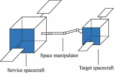
Fig.1 Illustration of the combined spacecraft.
However,many target spacecrafts in the OSS are noncooperative,which can cause an unknown shift of the mass center of the combined spacecraft.If the mass/inertia ratio of the non-cooperative target spacecraft to the service spacecraft is relatively large,the dynamics of the combined spacecraft will vary greatly.To solve the attitude control problem of unknown parameters,some control methods have been proposed.In Ref.10,online momentum-based estimation methods are used for inertia-parameter identification of the combined spacecraft.In Ref.11,a parameter identification based control scheme is designed to stabilize the combined spacecraft with an unknown tumbling target spacecraft with the help of the motion of the manipulator.In Ref.12,a continuous inertiafree control law is proposed for attitude tracking.In addition,a modified adaptive dynamic inverse attitude controller is proposed in Ref.13for a combined spacecraft with a large center of mass displacement and unknown inertia properties.
In Refs.6-13,all the attitude controllers of the combined spacecraft are model-based and based on the assumption that the connection between the service spacecraft and target spacecraft is fixed.In other words,the combined spacecraft is regarded as a rigid one. However, in reality, the noncooperative target spacecraft is not designed as a rigid one with custom grappling interfaces and visual makers;therefore,the connection between the target and service spacecrafts might be loose,causing the unknown motion of the target spacecraft.This phenomenon is known as partial constraints.The dynamics of the partially constrained combined spacecraft is strongly coupled,nonlinear and difficult to establish,so the modelbased control schemes become impractical for this combined spacecraft.
Fortunately,the combined spacecraft can generate huge amounts of Input/Output(I/O)measurement data containing all the valuable state information.This indicates that a datadriven controller can be designed without the modeling process.The term‘‘data driven”was first proposed in computer science.Although this term has only recently entered the vocabulary of the control community,data-driven control,such as virtual reference feedback tuning,14iterative learning,15and reinforcement learning,16has attracted extensive attention owing to its model-free merit.A data-driven control scheme,Model-Free Adaptive Control(MFAC)proposed by Hou,17has become an important research topic.It is independent of the model of the controlled plant and has fewer parameters than the other data-driven controllers,so it has been designed for various non-linear plants.18In MFAC design,a virtual equivalent dynamic linearization data model is built along the dynamic operation points of the closed-loop system by using a dynamic linearization technique.Then,the Pseudo-Partial Derivative(PPD),the resulting time-varying parameter in the data model,is estimated with only I/O data of the plant.However,the original MFAC algorithm does not consider the influences of disturbances,and thus is difficult to implement in the combined spacecraft which suffers from various types of external disturbances.19Accordingly,some improved methods have been developed.In Ref.20,the modified MFAC algorithm is studied to guarantee the robustness of the controller with bounded measurement disturbances. In Ref.21, a multiple adaptive observer-based MFAC is proposed with the consideration of disturbances in the input channel.However,until now the influences of disturbances have not been considered in the data-driven control system of combined spacecrafts.
An additional important problem for the attitude control of the combined spacecraft lies in actuator saturation.The output capacity of spacecraft actuator,such as thruster and reaction wheels,is limited;thus,the occurrence of actuator saturation will degrade the performance of the spacecraft and even destabilize the closed-loop system,if the service spacecraft is not equipped with an appropriate control scheme to avoid saturation.The actuator saturation of the spacecraft attitude control has been studied in Refs.22-24.Although all the solutions provided in these studies take actuator constraints into account,they are suitable only for model-based attitude control systems.Therefore,it is necessary to investigate the data-driven control with input saturation.
In this work,an attempt is made to provide a simple and robust data-driven attitude control strategy for the combined spacecraft in the presence of disturbances and actuator saturation.The main contributions of this study are as follows:
(1)the development of a novel dynamic linearization data model incorporating the disturbances of a combined spacecraft with partial constraints;
(2)the use of Discrete Extended State Observer(DESO)to eliminate the influences of unexpected disturbances;
(3)the use of anti-windup compensator to eliminate the input saturation;
(4)the design of a controller depending only on the input torque,output attitude,and angular velocity of the combined spacecraft with partial constraints.
The rest of this paper is organized as follows.Section 2 describes the problem of the combined spacecraft.Data-driven MFAC for the attitude control laws of the combined spacecraft is presented in Section 3.The main results are summarized in Section 4,and conclusions are given in Section 5.
2.Problem formulation and preliminaries
In this paper,we assume that the combined spacecraft system consists of two rigid spacecrafts,the service spacecraft and the target spacecraft.The target spacecraft is captured by the space manipulator installed on the service spacecraft,and has no custom grappling mechanical interfaces,resulting in loose connection between the target and service spacecrafts.In other words,all joints of the manipulator are locked except for the last one.The partial constraints lead to the unknown rotation of the target spacecraft.Note that the detailed model of the manipulator is not considered in this paper because the service spacecraft and the manipulator are treated as one unit.
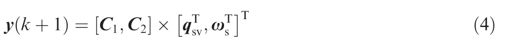
For the combined spacecraft attitude control in OOS missions,we only need to adjust the attitude of the service spacecraft to the desired attitude,without considering the attitude of the target spacecraft.Thus,the attitude kinematics of the service spacecraft can be regarded as that of the combined spacecraft.
As in Ref.25,the unit quaternion is used to represent the attitude kinematics of the combined spacecraft:

For the combined spacecraft without partial constraints,the combination system can be considered as a rigid one.However,the combined spacecraft with partial constraints is no longer a rigid one,leading to the unknown rotation of the target spacecraft;therefore,the traditional rigid model is inadequate to describe the combined spacecraft dynamics.Considering the partial constraints,we reestablish the Euler's dynamical attitude equation of the combined spacecraft,26,27as shown below:
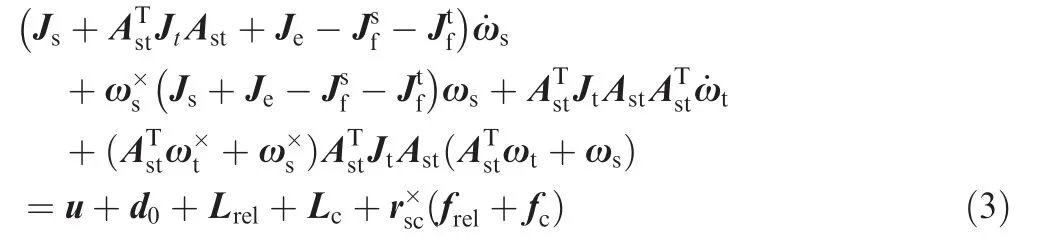
where Jsdenotes the total inertia matrix of the service spacecraft,Jtthe total inertia matrix of the target spacecraft,ωtthe angular velocity of the target spacecraft body frame with respect to the service spacecraft frame,and Jethe additional inertia matrix caused by the target spacecraft.andare the inertia matrixes of mass migration,caused by the service spacecraft and target spacecraft,respectively.Lrelis the additional torque,Lcis the additional coriolis torque,frelis the additional force,fcis the additional coriolis force,u is the control torque vector,d0is the torque vector of external disturbances,unknown but bounded,rscis the position vector from the center of the service spacecraft mass s to the center of the target spacecraft mass c,and Astis the transformation matrix from the service spacecraft to the target spacecraft.
The I/O relation of the combined spacecraft can be rewritten in the following discrete-time unknown Multi-Input Multi-Output(MIMO)Nonlinear Autoregressive Exogenous Model(NARX):
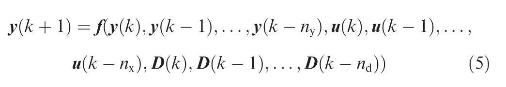
where the lumped disturbances D=d0+Lrel+Lc+,and ndare the unknown orders,and f(·)is an unknown nonlinear function.Obviously,the combined spacecraft system meets the following assumption.
Assumption 1.Ref.18the combined spacecraft system Eq.(5)is generalized Lipschitz,which satisfies Eqs.(6)and(7)for any k1>0 and k2>0,and k1≠k2.
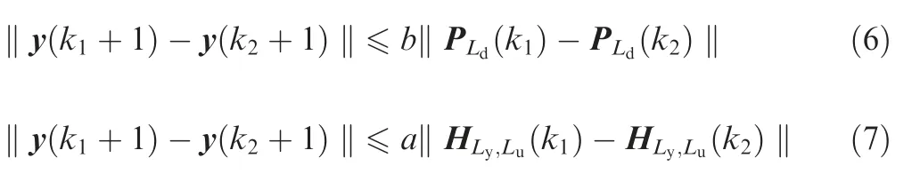
where a and b are positive constants,and
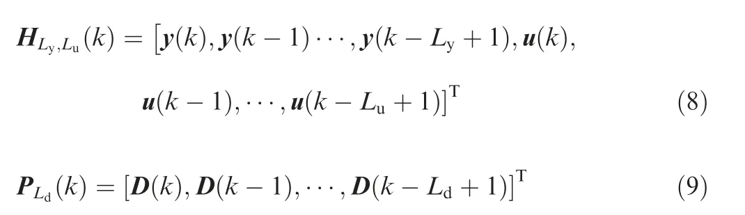
where Ly,Luand Ldare positive constants.
Before describing the control law design,we define the virtual equivalent dynamic linearization data model of the combined spacecraft in Lemma 1.
Lemma 1.Satisfying Assumption 1 for every discrete time of the kth moment,the combined system Eq.(5)can be transformed into the following full-form model of equivalent dynamic linearization data:

where φLy,Lu(k)is the PPD matrix,γ0(k)is the unknown additional disturbance matrix,Δy(k+1)=y(k+1)-y(k),and
Proof.See Appendix A.□
Remark 1.Lemma 1 is inspired by Ref.28,but it considers the influences of disturbances.The data model in Lemma 1 is a more general form and can be seen as an improvement of Ref.28
3.Control law design
In this section,we will introduce an improved MFAC.Considering the spacecraft attitude system given by Eq.(5),the control objective is to design the control input u(k).Under all physically realizable initial conditions, the states of the closed-loop system are stable, which can be expressed as
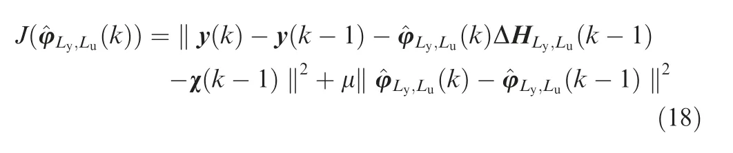
Our goal is to control the attitude of the combined spacecraft,using only the I/O measurement data of the system.The control performance is evaluated by the minimization of the following function:
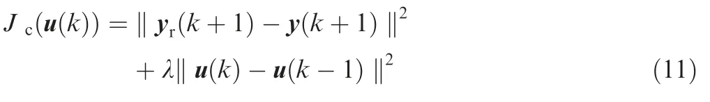
where yr(k+1)is the desired output signal,and λ >0 is a weighting constant.
Substituting Eq.(10)into Eq.(11),differentiating Eq.(11)with respect to u(k),and setting it to zero yield
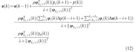
where ρ ∈ (0,1 ],which is a step-size constant,added to generalize Eq.(12).
The control law Eq.(12)is designed merely by I/O data of the combined spacecraft,and has a recursive form.It has no relations with any explicit model dynamics and structural information of the combined spacecraft.However,the disturbance matrix γ0(k)and PPD φ(k)are unknown;thus,the observer and estimator will be used to estimate the unknown part of the controller in the following subsection.
3.1.Discrete extended state observer design
In order to estimate the unknown disturbances,the DESO is exploited.Define φLy,Lu(k)as


To design the DESO,the following reasonable assumption is made:
Assumption 2.For any kth or(k+1)th moment,there always exists a constant μ1such that ‖Δγ(k+1)‖=‖γ(k+1)-γ(k)‖≤μ1.
To estimate the uncertainty term γ(k),the following lemma should be recalled.

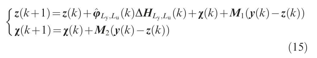
where z(k+1) and χ(k+1) are the observed values of y(k+1)and γ(k+1),respectively,and M1and M2are the appropriate parameters.
Proof.Define the observer error as
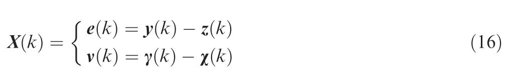
Substituting Eqs.(14)and(15)into Eq.(16),one obtains

The appropriate values of the parameters should be chosen that the eigenvalue values of ADESOare less than 1.Then,according to Assumption 2, the observer error ν(k) is bounded, namely limk→∞‖ν(k)‖≤μ2, where μ2is an unknown positive constant.□
3.2.PPD matrix estimator design
In Eq.(10),φ(k)is unknown and the modified projection algorithm is recalled to estimate^φ(k).The performance function for the unknown PPD estimation is defined as
where the weighing factor μ >0.Differentiating Eq.(18)with respect to φ(k),and letting it be zero,one obtains
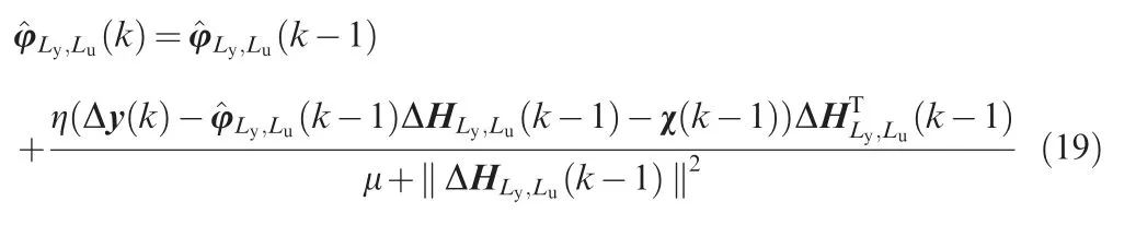
where η ∈ (0,1 ],which is a step-size constant,added to generalize Eq.(19).
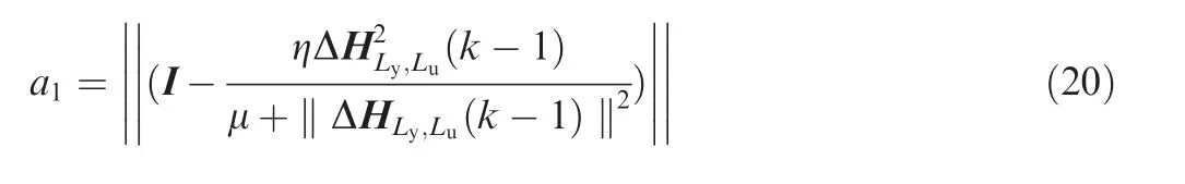
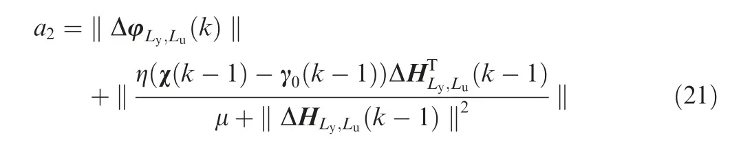
To guarantee that the estimation erroris bounded,the following lemma is proposed.
Lemma 3.Given the combined spacecraft attitude model governed by Eq.(14)with the estimator Eq.(19),the estimation erroris bounded for all the kth moments with bounds,namely
Based on the DESO Eq.(15)and the PPD estimator Eq.(19),the data-driven unconstrained control law is calculated in Eq.(27):

Proof.Substituting Eq.(19)into Eq.(13)yields
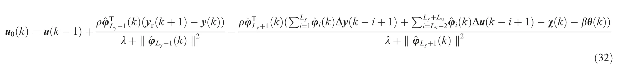
3.3.Data-driven controller design with actuator saturation
Actuator saturation,a serious problem in spacecraft applications,is inevitable in that some control torques are unachievable for practical actuators.In this section,by introducing an auxiliary anti-windup variable,we design another datadriven control scheme,which achieves high performance in the presence of actuator saturation.
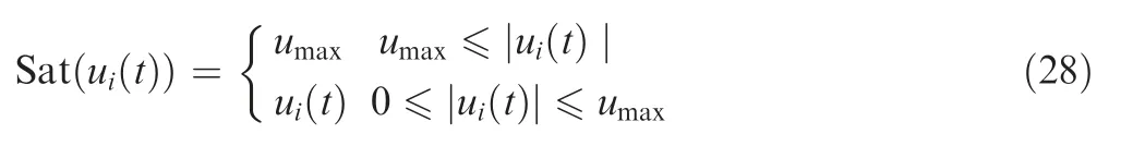
Considering actuator saturation,the actual actuator control vector is described as Sat(u) =in which Sat(ui(k)),i=1,2,3 is defined as
In view of Eq.(10),one obtains
According to the norm inequalities,Eq.(23)can be easily described as follows:
In view of Eq.(6)and Lemma 2,one has
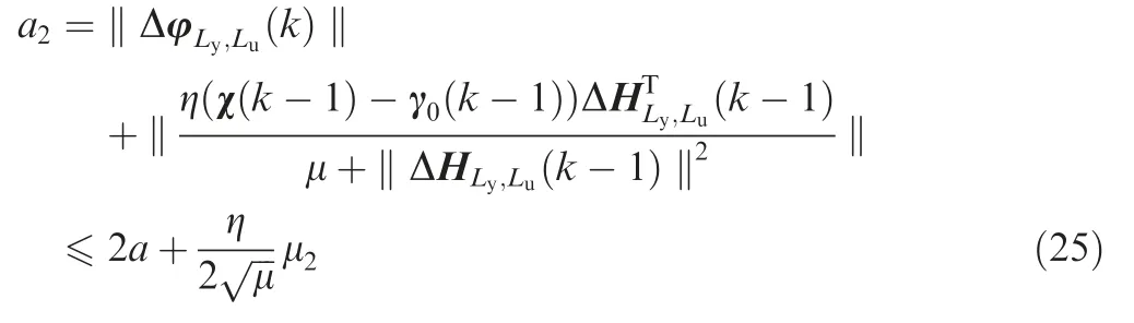
For each kth moment,one has the following inequality
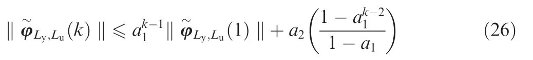
Because a1∈(0,1)and due to Eq.(25),the results of the observer error system are bounded for all the k, namely
As a result of the dynamic constraints in the close-loop combined spacecraft attitude control,an anti-windup compensator is proposed to adjust the reference trajectory yr(k).The compensation signal θ(k)is designed as follows:

where β ∈ (0,1 ].Then the following theorem can be derived.
Theorem 1.For the combined spacecraft system Eq.(10)with the controller,the DESO Eq.(15)and the PPD estimator Eq.(19),the close-loop attitude tracking error is bounded for all the kth moments with ultimate bounds limk→∞‖e(k)‖≤a4/(1-a3).
Proof.Define the tracking error e(k)as

where y*(k)=yr(k)+θ(k).
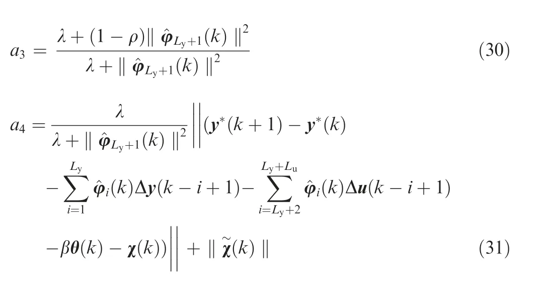
Substituting Eqs.(10)and(29)into the tracking error Eq.(33)yields
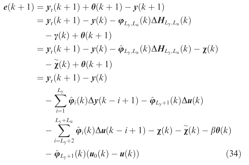
Substituting Eq.(32)into Eq.(34)gives
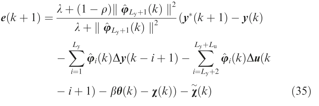
Taking the norm of Eq.(35),one obtains
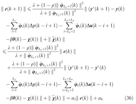
Since 0 ≤a3<1 and a4is bounded,under the constrained control law Eq.(32)and the compensation signal Eq.(29),we can draw a conclusion through a similar analysis in Lemma 3 that the results of the close-loop system Eq.(10)are bounded for all thek with ultimate bounds limk→∞‖e(k)‖≤a4/(1-a3).
A block diagram is shown in Fig.2 to illustrate the overall design of the attitude control system of the combined spacecraft.
4.Simulation and analysis
In this section,numerical simulations are presented to verify the effectiveness of the proposed data-driven controller.The initial quaternions of the service spacecraft and target spacecraft are set as qsv(0)=[0 .0 34,0.153,0.091]Tand qtv(0)=[0 ,0,0]T,respectively.The initial angular velocity of the service spacecraft and target spacecraft are set as ωs(0)=[0 .0 1,0.01,0.01]Trad/s and ωt(0)=[0.02,0.01,-0.01]Trad/s,respectively.The desired states of the combined spacecraft are qsd=[0 ,0,0]Tand ωsd=[0 ,0,0]T,respectively.Table 1 lists the parameters used for the simulations.
The following external disturbances are introduced to analyze the robustness of the proposed controller:

Case A:In this case,the robustness of the proposed controller is studied.In order to illustrate the performance of the proposed data-driven control law,we examine the performance of the proposed controller and the PD controller.We assume that the mass of the target spacecraft changes at 120 s from 100 kg and [5 0, 0,0;0,100,0;0,0,100]to 200 kg and [1 00 ,0,0;0,200,0;0,0,200].Note that the input saturation is not considered in this case.The parameters of the datadriven controller are set as ρ=0.5,λ=0.5,η=0.1,μ=1,Ly=1,Lu=1,C1=25I3,C2=80I3,φ1(1)=φ1(2)=40I3,and φ2(1)=φ2(2)=5I3.The PD controller parameters are set as kP=8I3,and kd=60I3.kPand kdare chosen by trial and error in order to achieve the same attitude response performance with the data-driven controller when the mass of target spacecraft is 100 kg.The settling time for both controllers is 350 s,which can be seen in Figs.3(a)and(b),Figs.4(a)and(b),and Figs.5(a)and(b).This means that the two controllers perform equally when there is no additional uncertainty in the combined spacecraft.
The responses of the service spacecraft attitude and the angular velocity are shown in Figs.3(c)and(d)and Figs.4(c)and(d),respectively.Figs.3(c)and(d)show that the settling time of the proposed controller and of the PD controller is 350 s and more than 600 s,respectively,when the mass of the combined spacecraft changes during the simulation.The same result can also be seen in Figs.4(c)and(d).These results show that the uncertainty caused by the target spacecraft has only a slight impact on the performance of the proposed controller.The proposed controller performs better than the PD controller due to the ability to adjust the controller parameters according to the system changes in time and to output a proper control torque.This can be seen in the control torque curves(Figs.5(c)and(d))which show that the actuator output derived from the proposed strategy has a faster response than that of the PD controller when uncertainty occurs at 120 s.Thus,the proposed controller can provide a faster convergence rate and a better robustness than the PD controller.
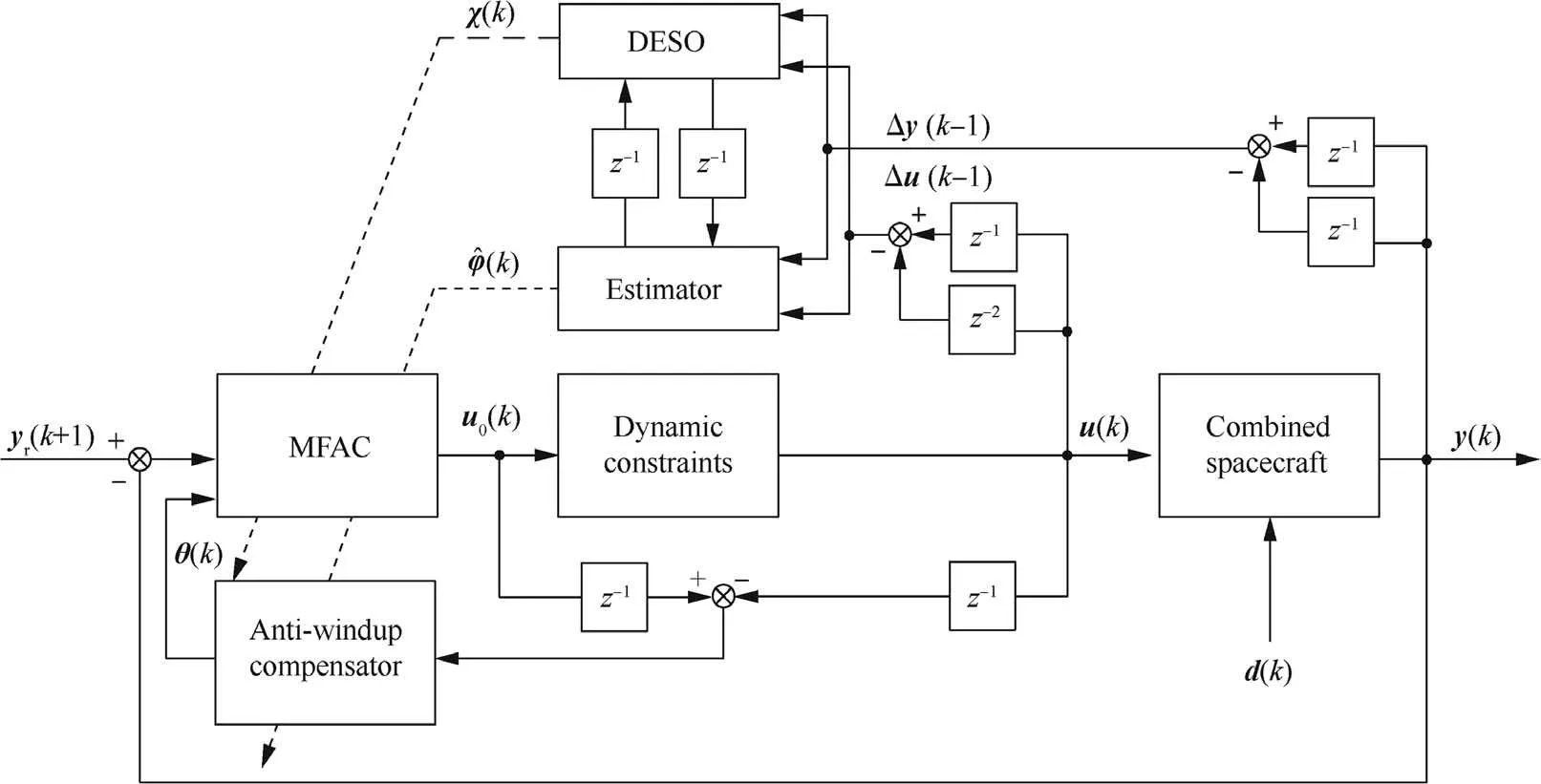
Fig.2 Block diagram.

Table 1 Simulation parameters.
Case B:In actual missions,controller parameters are chosen according to the nominal parameters of the combined spacecraft in the ground test,and can hardly be changed once selected.However,these parameters may not be suitable for all the situations since the target spacecraft is usually unknown.Thus,an adaptive controller is more preferable.In order to illustrate the performance of the proposed data-driven control law,we add the traditional MFAC for another comparison.For a fair comparison in this case,the same controller parameters are selected for both the data-driven and the PD controller with C1=kP=8I3and C2=kd=80I3. The remaining parameters of the proposed data-driven controller Eq.(32)and traditional MFA controller are ρ=0.5,λ=0.5,η=0.1, μ=1, Ly=1, Lu=1, φ1(1)=φ1(2)=40I3, and φ2(1)=φ2(2)=5I3. The observer and anti-windup compensator parameters are M1=0.2diag(1,1,1),M2=0.01diag(1,1,1)and β=0.2.Additionally,the reaction wheel is chosen as the actuator,and the maximum torque available is set to be 0.3 N·m.
Simulations are conducted and the results are illustrated in Figs.6-10.Fig.6 shows the responses of the service spacecraft attitude of the proposed data-driven controller,the traditional MFA controller,and the PD controller;Fig.7 displays the responses of the attitude angular velocity.In the case without actuator saturation,it is found that the settling time of the proposed controller and of the other controllers is less than 300 s and more than 300 s,respectively.In the case with actuator saturation,it is found that the settling time of the proposed controller is less than 400 s and the settling time of the other controllers are more than 500 s.Moreover,the steady-state errors of the proposed controller,and| ω|≤2×10⁻⁴(°)/s,are smaller than those of the PD controller,|q|≤5×10⁻⁶and |ω |≤5×10⁻⁴(°)/s.These simulation results demonstrate that the performance of the proposed controller is always better than that of the PD and MFAC with or without actuator saturation.More importantly,the proposed controller is more applicable than the other controllers when the controller parameters are not well designed for an unknown combined spacecraft.The proposed controller is thus useful for a practical system.Further,the control input curves(Fig.8)show that the proposed controller has less energy consumption than the other two controllers.This is another important advantage of the proposed controller.Thus,the proposed data-driven controller is efficacious in terms of convergence speed and steady precision,and even when external disturbances and actuator saturation act on the combined spacecraft.
Fig.9 presents the PPD estimation of the combined spacecraft system without and with actuator saturation It can be observed that the PPD estimator adjusts the estimation values in different situations,but the proposed data-driven controller can provide suitable torques.
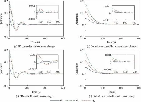
Fig.3 Time responses of combined spacecraft attitude in Case A.
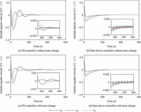
Fig.4 Time responses of angular velocity of combined spacecraft attitude in Case A.
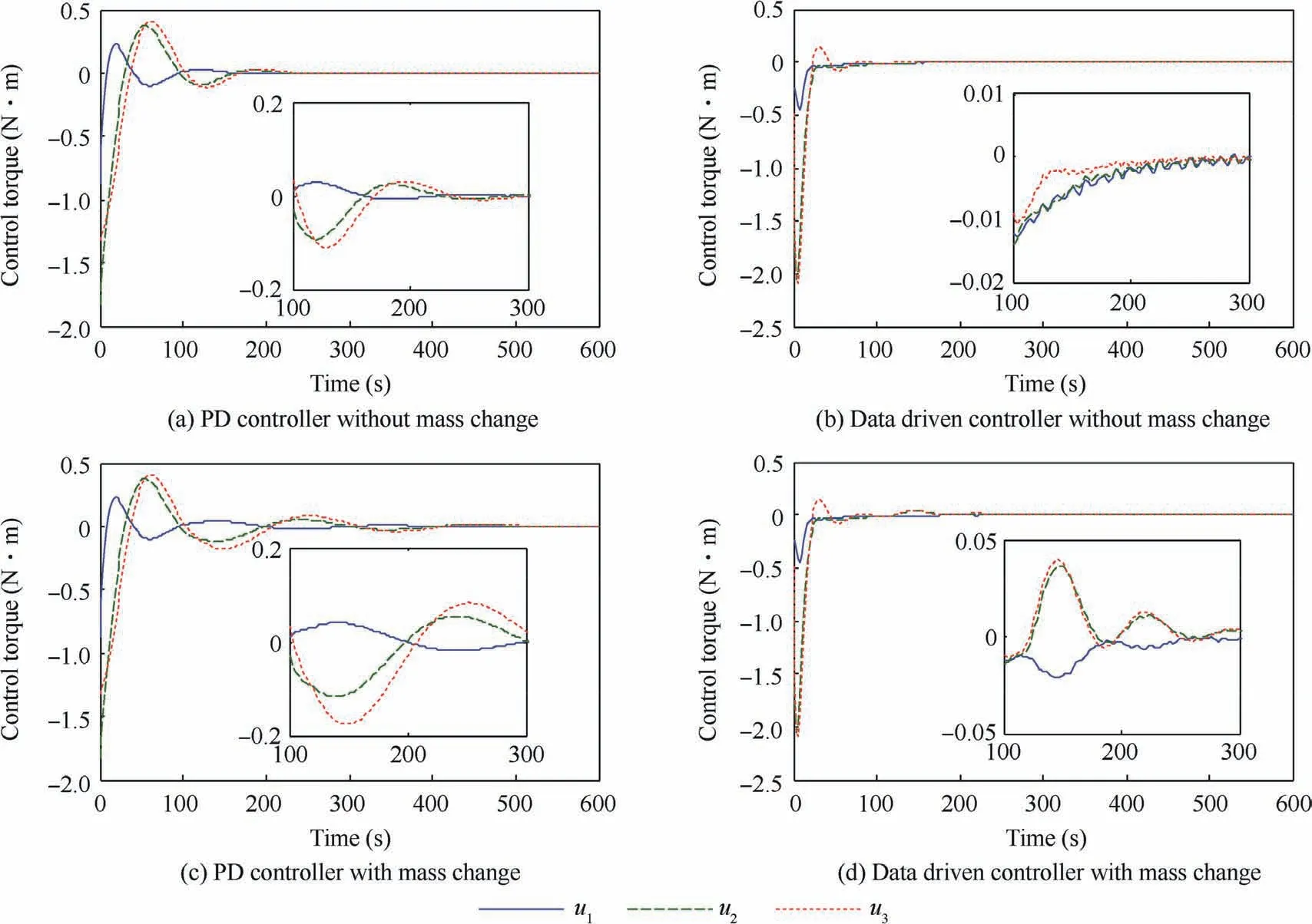
Fig.5 Time responses of combined spacecraft control torques in Case A.
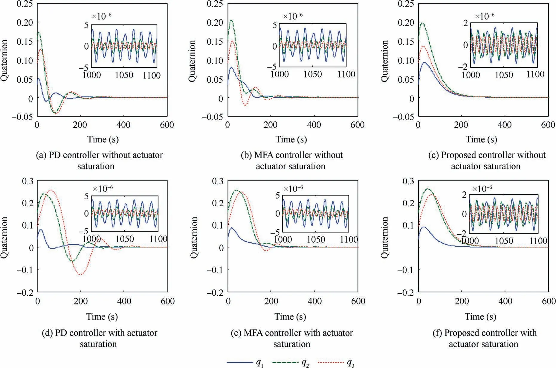
Fig.6 Time responses of combined spacecraft attitude in Case B.
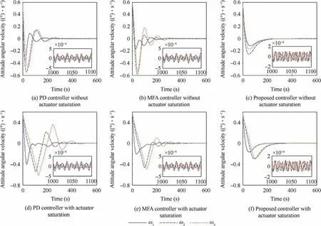
Fig.7 Time responses of angular velocity of combined spacecraft attitude in Case B.
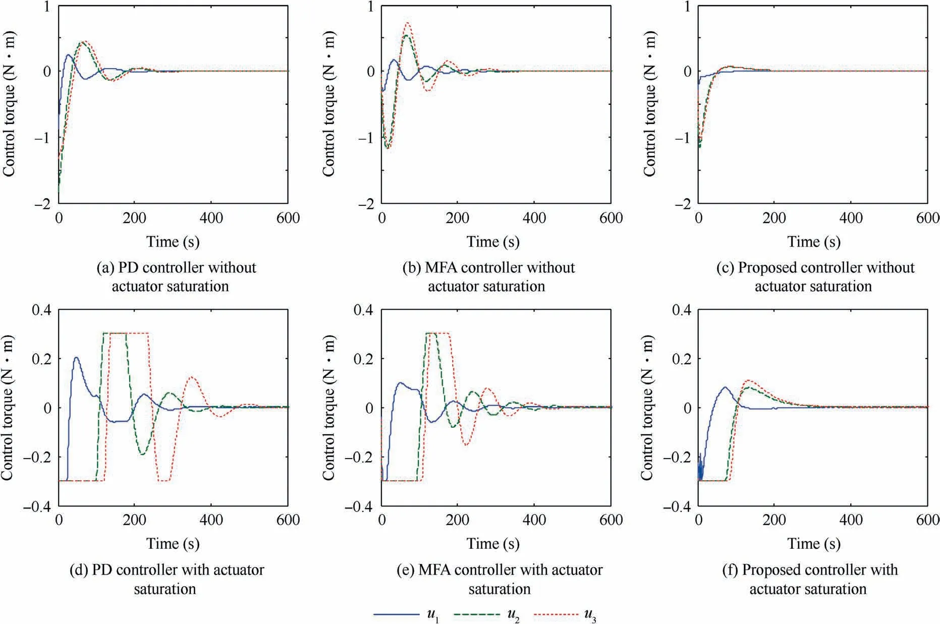
Fig.8 Time responses of combined spacecraft control torques in Case B.
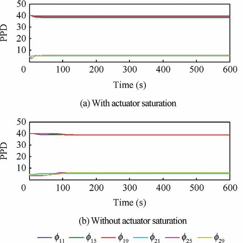
Fig.9 Time responses of PPD.
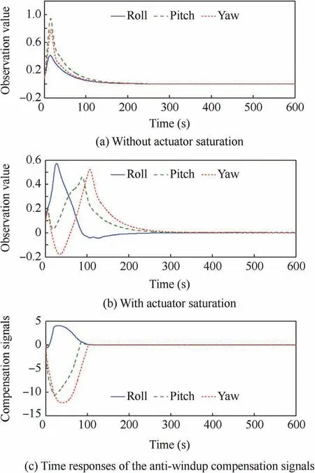
Fig.10 Time responses of observation value and compensation signal.
Furthermore,Fig.10 shows the observed values of the total disturbance of the combined spacecraft system without and with actuator saturation and the time responses of saturation compensation signals.From Fig.10,it can be seen that the states of the disturbance observer and saturation compensator converge to small neighborhoods of zero with high performance of transient and steady-state responses.This means that the proposed observer and compensator can ensure the stability of the overall system.
Summarizing the two cases,we can conclude that the proposed scheme can successfully accomplish attitude stabilization with a high stability and fast convergence rate in the presence of unknown dynamics,external disturbances,and even actuator input constraints in numerical simulations.
5.Conclusions
This paper proposes a novel data-driven attitude control for the combined spacecraft based on MFAC that incorporates DESO and the anti-windup scheme.The proposed controller is particularly effective while the analytical model of the combined spacecraft is difficult to develop.In the basic controller design,an attempt is made to combine the MFAC with the DESO to accomplish data-driven control.External disturbances are adequately addressed within the proposed framework.A simple algorithm is then developed for the actuator saturation scenarios. Once actuator saturation occurs, an anti-windup compensator designed can solve the problem of saturation.Numerical simulations have been carried out to validate the feasibility of the data-driven controller proposed.However,the actuator faults such as loss of effectiveness or biases are not considered in this paper,which can be investigated in the future research.
Acknowledgements
The authors would like to thank the editor and all the anonymous reviewers for their valuable suggestions that helped to improve the quality of the manuscript.This research is supported by National Natural Science Foundation of China(Nos.61603114,61673135),and the Fundamental Research Funds for the Central Universities of China (No. HIT.NSRIF.201826).
Appendix A.
Proof.Since

substituting Eq.(5)in Eq.(A1)gives

Note that
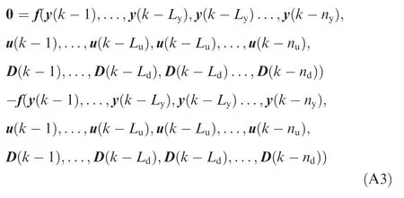
Substituting the zero equality Eq.(A3)into Eq.(A2)yields
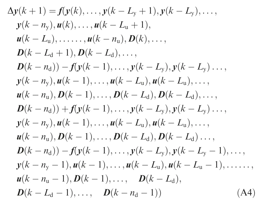
Let
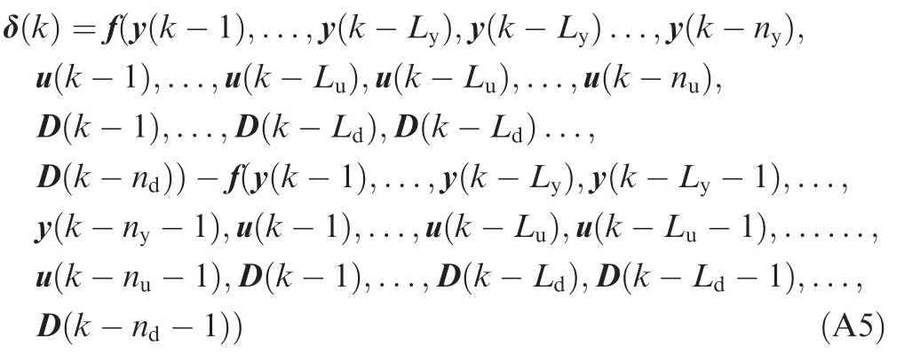
According to Assumption 1 and Cauchy differential mean value theorem,one has
Given that ΔHLy,Lu(k)≠0 and ΔPLd(k)≠0,Eq.(A5)can be further rewritten as

where σ1(k)and σ2(k)are unknown coefficient matrixes.
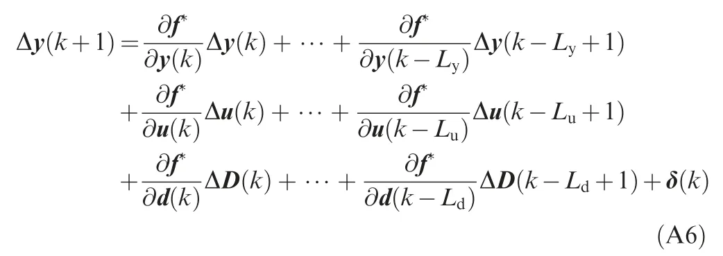
Substituting Eq.(A7)into Eq.(A6)yields

where the parameters φLy,Lu(k)and ψLd(k)are given by
Let ψLd(k)ΔPLd(k)=γ0(k),and then we have Eq.(10).
 CHINESE JOURNAL OF AERONAUTICS2019年5期
- CHINESE JOURNAL OF AERONAUTICS的其它文章
- Guide for Authors
- Effect of W addition on phase transformation and microstructure of powder metallurgic Ti-22Al-25Nb alloys during quenching and furnace cooling
- Thermoelastohydrodynamic analysis of misaligned bearings with texture on journal surface under high-speed and heavy-load conditions
- Role of the inter-pass cooling rate in recrystallization behaviors of Ni-based superalloy during interrupted hot compression
- Crystal orientation and morphology of α lamellae in wrought titanium alloys:On the role of microstructure evolution in β processing
- Three-dimensional finite-time cooperative guidance for multiple missiles without radial velocity measurements