Nonlinear dynamic characteristics of a multi-module floating airport with rigid-flexible connections *
Dao-lin Xu (徐道臨), Hai-cheng Zhang (張海成), Shu-yan Xia (夏淑炎), Chao Lu (盧超),En-rong Qi (祁恩榮), Chao Tian (田超), You-sheng Wu (吳有生)
1. State Key Laboratory of Advanced Design and Manufacturing for Vehicle Body, Hunan University, Changsha 410082, China, E-mail: zhanghc@hnu.edu.cn
2. China Ship Scientific Research Center, Wuxi 214082, China
Abstract: This paper studies the dynamics of a multi-module floating airport with flexible connectors using the network theory.A mathematical model for a chain-type topology structure is developed by using the wave theory, and the models of a single floating module and the connector and mooring system.The nonlinear dynamics of the floating airport and the connector force are studied.A remarkable phenomenon of amplitude death is observed, as a weak oscillation state of all floating modules, an important state for the system global dynamic stability.The parametric domain for the onset of amplitude death is identified, and the effects of the wave height and the number of the floating modules on the dynamic stability are discussed.An application of the network theory in the marine engineering is illustrated with the introduction of a new concept for global dynamic stability for the floating airport.
Key words: Floating airport, network dynamics, amplitude death, rigid-flexible connection
Introduction
With the growing population and the corresponding urban expansion in land-scarce regions, very large floating structures (VLFs) were proposed for the land reclamation from the sea in order to ease the pressure on the existing heavily-used land space due to their relatively simple construction and easy maintenance.The VLFS gradually comes into applications in the forms such as the floating bridges, the floating airport, the floating cities, the floating fuel storage facilities[1].The design of an effective VLFS with consideration of safety and performance is the key phase for the successful implementation, the operation and the further development.Some applications involve stringent tolerances on the floating structures.We take the floating runway in the Mega-float project as an example, the slope of the structure in the longitudinal direction is required to be less than one degree[2].Thus the reasonable prediction of the dynamic characteristics of the VLFS is important for its implementation.
Various methods were proposed to predict the dynamic response of the floating structures in waves.Since the pioneering work-on the motion of a floating rigid thin plane slab, there have been extensive research activities on the analysis of very large floating structures.With consideration of the elasticity of the VLFS, the hydroelastic theory was adopted for the dynamic response analysis of the floating structure[3].Some researchers[4]dealt with the VLFS as floating beams.Most researchers dealt with the pontoon-type VLFS as a thin plate based on the Kirchhoff’s plate assumptions where the plate model is treated as either an isotropic or orthotropic plate.The floating structures discussed above are all treated as a single module, and the analysis is based on the linearized modal superposition or the finite element discretization method.Since a single module VLFS is massive in size, and may cause extremely high internal stress, the multiple module platform with flexible connections are preferred due to their easy construction, transportation and deployment[1], however, one has to deal with the connection problem.Maeda et al.(1979) studied the dynamic behaviors of floating structures, consisting of a number of rigid modules with rigid or pin connectors, in heave and pitch motions in regular waves by using the strip method.It is shown that smaller response amplitudes are obtained with rigid joints than with pin joints.On the other hand, the amplitudes of the shear force and the bending moment are smaller with pin joints than with rigid joints.Riggs and Ertekin[5]developed a three-dimensional hydroelastic model of a multimodular floating structure in regular waves with an arbitrary angle by using the FEM for the structures and a strip method for the fluid.The connector is represented by a linearized stiffness matrix with respect to the displacements at the module connection points.Xia et al.[6]dealt with the VLFS as a number of two-dimensional articulated plates connected by connectors idealized as two independent vertical and rotational springs.It is shown that the hydroelastic dynamics are strongly dependent on the stiffness of the connectors and the incoming wave frequency.The optimum configuration of a modular floating structure with flexible connectors, modeled as two linearized springs in longitudinal and/or transverse directions,was investigated by Michailides et al.[7].The analysis results of three grid types of the floating structure show that the grid types (the number and the layout of modules) directly affect the internal loads in the connectors and the responses of the modules.The dynamic responses of the VLFS were widely studied not limited to the above mentioned cases.Some reviews[1,8-10]give more details.Note that most of the previous studies dealt with the connectors as independent linear springs in all degrees of freedom or a discretized stiffness matrix using the FEM method,ignoring the coupling effect among the module motions in different directions and the nonlinearity of the stiffness.In fact, the stiffness of connectors is dependent upon both the elasticity of materials and the relative displacements between adjacent modules.Because the relative displacements between adjacent modules are not small, thus a displacement in a specified direction is also dependent on the displacements in other degrees of freedom and the displacements are actually coupled, due to the geometrical nonlinearity[11].
A floating airport consists of multiple floating modules that are elastically connected (coupled) by connectors in a serial configuration.Each module in waves can be viewed as an oscillator and the integrated platform of the connected modules can be regarded as a typical network.Based on the nonlinear network theory, it was reported[11-12]that the coupling effect could significantly influence the dynamics prediction of the floating airport.These preliminary studies also indicate that the classic linear theory may greatly underestimate the actual responses and loads on the structure of the floating airport.With rubbercable type connectors, complex dynamical behaviors were observed, including the sudden changes of module responses and connector loads[11], the amplitude death for the global dynamic stability[12], the synchronous phenomena of responses among floating modules and the coupling synergistic effect of network dynamics[13].These studies are the initial attempt of using nonlinear network theory in the marine engineering as methodology in the prediction of the dynamics response of the VLFS.Especially, the amplitude death that corresponds to a collective weak oscillation state offers a new concept for the global stability design of the floating airport, and could be extended to many other engineering problems with similar network structures.
In a effort to explore the new methodology, this paper extends the study of the nonlinear dynamics of the floating airport to the cases of three degrees of freedom in surge, heave and pitch motions, while the previous studies[11-13]only considered surge and heave motions.In addition, a new type of connector design is considered in this paper, which is a geometrically parallel configuration hinged to the floating modules for the connection.A chain-typed network model of the floating airport is developed based on the linear wave theory, the dynamic model for a single floating module, the mechanical model of the new connector and the model of a mooring system.The dynamic response and the connector loads of the floating airport are analyzed by numerical simulations.The phenomenon of amplitude death (AD) observed is typically referred to the state of the oscillation suppression in non-autonomous networks[14]due to the interaction among coupled oscillators in the networks.The AD means that the responses of all floating modules are simultaneously trapped into a very weak oscillation state, indicating an extraordinary state of the global stability of the floating airport.This paper further discusses the onset condition for the amplitude death of the floating airport with illustrations of numerical results.The modeling method introduced in this paper is not limited to the applications with respect to the chain-type floating airport and it is theoretically suitable for all kinds of VLFS with complex topology network structures.
1.Network model of floating airport
In this paper, the floating airport is considered as a chain-type network system which consists of rigid modules with flexible connectors (RMFC).The two ends of the network system are constrained by mooring lines which are considered as elastically constrained boundary conditions.Figure 1 shows the model sketch in the Cartesian coordinates withxaxis on the undisturbed free-surface plane aligned with the longitudinal direction of the floating airport andz-axis in the upward direction.In this section,the dynamic model of a single floating body and the mechanical model of the connector are developed, and then the network dynamic model of the entire floating airport is constructed by integrating the models and the mooring constraint conditions and the topology connection matrix of the floating airport.

Fig.1 Sketch of the multi-module floating airport
1.1 Model of single floating module
This paper considers a two-dimensional problem in surge, heave and pitch motions.For a single module oscillator, by applying the linear wave theory[15], we can formulate a governing equation of motion for a floating module, as

whereX=[x,z,β]Tis the displacement vector of the module, where the symbolsx,z,βindicate the displacement components of surge, heave and pitch motions, respectively and the superscript T denotes the transpose.MandSdenote the mass matrix and the hydrostatic restoring coefficient matrix,respectively
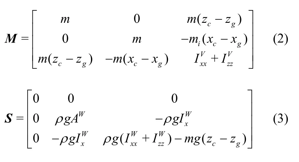
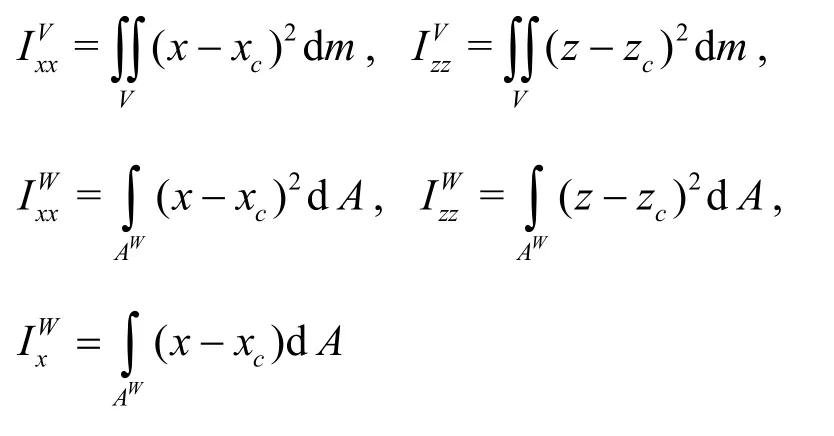
wheremis the mass of the floating module,ρis the density of the water, andgis the gravitational acceleration.(xc,zc) and (xg,zg) denote the coordinates of the rotation center and the gravity center, respectively.WAandVindicate the water plane area and the submerged volume of the module,respectively and we haveAW=L,V=Ldfor the two-dimensional problem, whereL,ddenote the body length and the sub-depth of the module.The first and second moments of inertia of the water plane area and the submerged volume with respect to the rotation centerare defined as below[16]
The symbolwFin the right hand side of Eq.(1) indicates the wave force on the module.For a linear head wave of heighta, and wave regular frequencyω=2π|T, whereTis the wave period,the total wave potential can be separated into the incident potential, the diffraction potential and the radiation potential[15].The matricesμ,λin Eq.(1)represent the added mass and the added damping,respectively as a result of the radiation potential due to the motion of the module, and their elements can be determined by using the eigen-function expansion matching method[17].The wave forcewFon the floating mo- dule can be obtained by integrating the incident potential and the diffraction potential along its wet surface.The incident and diffraction wave potentials mainly contribute to the periodic excitation force, while the effect of the scattered wave potential is not considered here for the reason of simplicity, as the main attempt in this work is to illustrate the feasibility of the network theory for the dynamic prediction of the floating airport.The effect of the scattered wave potential is discussed in a very recent study[18].Thus the wave force can be written as

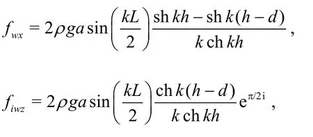

wherehis the water depth,kis the wave number satisfying the dispersion relation ω2=gkthkh.
The last two termsFc,Fmin Eq.(1) are the forces on the module due to the flexible connector and the mooring system, which will be derived latter in details.Since the modeling of a single floating body is well-developed, and the related derivation can be found in references[19], we do not go into more details here.
1.2 Model of the flexible connector
One of key steps for developing a model of the multi-module floating airport is to formulate the mechanical model of connectors between adjacent modules.In this paper, the coupling model consists of two elastic hinge-type connectors, as shown in Fig.2(a).The two connectors are positioned parallel at a vertical distance2δand the two endpoints of each connector are hinged with modules.The distance between adjacent modules isδthat is equal to the initial length of the connector.The RMFC model allows surge, heave and pitch motions of floating mo- dules.
Before formulating the mathematical model, we first define a local coordinate system (Xi,Zi) for thei- th module.The rotation center of the resting floating module is defined as the origin of the coordinates,Xiaxis is parallel to the undisturbed free-surface andZiaxis points upwards.The sketch of the coordinates and the position relationship for adjacent modules is shown in Fig.2(b).
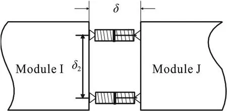
Fig.2(a) Sketch for the coupled connectors

Fig.2(b) the position relationship for adjacent modules
The adjacent modules are simplified as two triangles.The triangle of dashed line denotes the initial position and that of solid line represents the position after the deformation with the displacement(xi,zi,βi) and (xj,zj,βj).The solid circles denote the rotation centers of the adjacent modules and the hollow circles denote the hinge joints.The solid lines labeled withdenote the connectors.The pitch angleβof each module is a small quantity due to the huge scale of the module, so we have

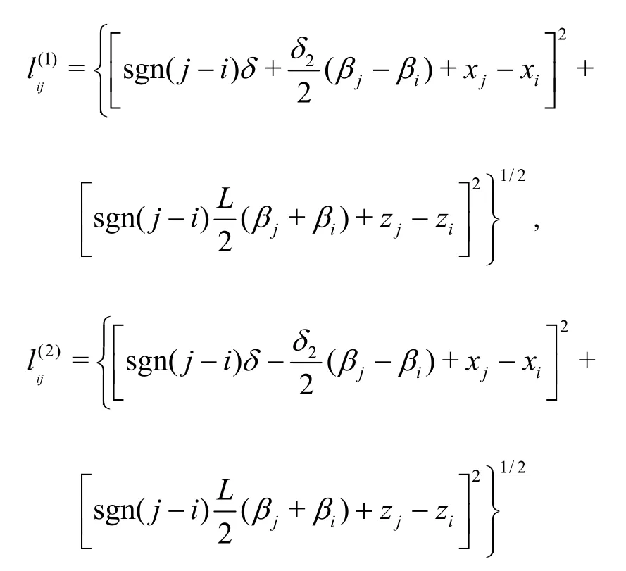
In what follows, we will formulate the mechanical model of the coupled connectors based on an approximation of Eq.(6).In view of the geometric relationship of adjacent modules, the deformation of the connectorsare expressed as

where
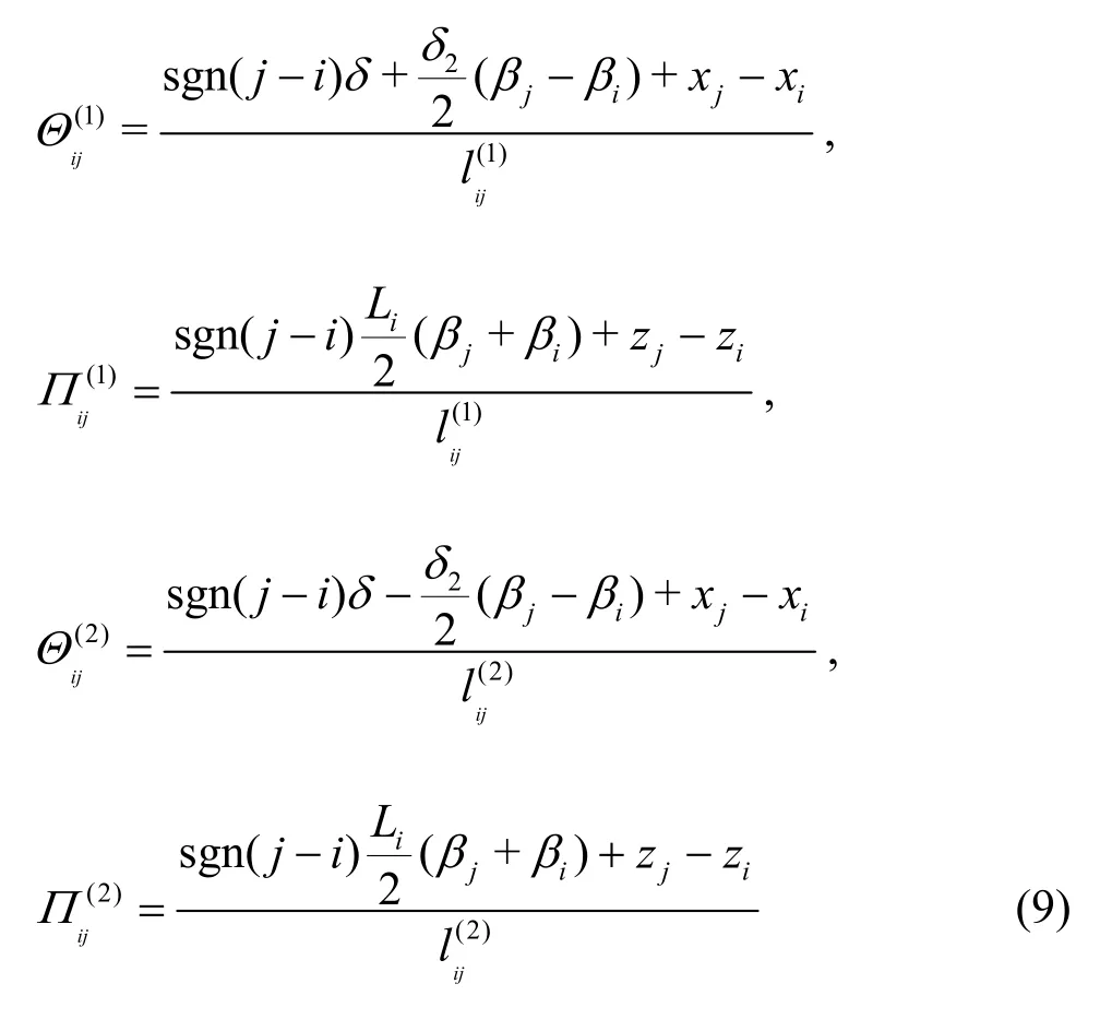
The direction vector for the projection of the connector deformation is formulated as

wherei,jdenote the unit vectors inx,zaxes anddenote the deformation coefficients in the surge and heave directions, respectively
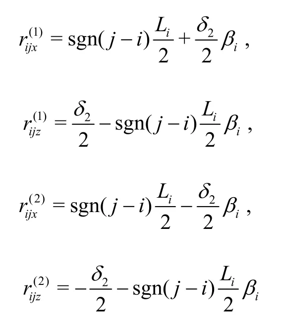
The vector of the force arm with respect to the rotation center of thei-th module for the connector forces is

where
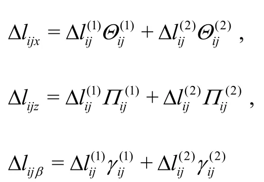
The vector of the moment on the rotation center of thei-th module for the connector forces is

wherekdenotes the unit vector inyaxis anddenotes the deformation coefficient in the pitch direction.Substituting Eq.(8) and (10) into Eq.(11),we obtain

In this paper, we assume that a single connector has a linear stiffnesskcalong its longitudinal direction, thus the force of the coupled connectors on thei-th module takes the form

where
Right now, the mechanical model is formulated for the coupled connectors in Eq.(13).Note that the model of the coupled connectors contains some nonlinear geometric characteristics.It should be noted that the displacements at the hinge joints are very large even if the pitch angles of the modules are small due to the huge scale of the modules.Thus the model of the connector presents strong nonlinearity.On the other hand, the stiffness of the connection between adjacent modules in a specified degree of freedom depends on the motions in other degrees of freedom even if the elasticity of a single connector is linear.
1.3 Model of mooring system
In order to prevent drifting, the floating structure is constrained by a mooring system.Various types of mooring systems are proposed over the past few decades.In this paper, we choose a simple mooring system named the slack catenary line in this paper.The mooring line tension on the floating module is represented as a linear function of the displacement by using the integrated equations of the deep sea mooring lines in the static equilibrium.The derivation of the linearized stiffness coefficients of the mooring matrixfollows the simplified method suggested by Sannasiraj[20].It is assumed that the mooring line is perfectly flexible, inextensible and in the heave direction.
The sketch in Fig.3 shows a two-dimensional floating structure moored by the catenary line of lengthH.The mooring line is anchored at the pointBwith a bottom angle0θand the other end is attached at the pointQof the floating module.The catenary line is extended hypothetically beyondBfor a lengthltoB′, so that the angleθatB′ is zero.Two sets of rectangular coordinates (ξ,)?and(χ,)Ωare chosen in the plane of the catenary line throughBandB′, respectively.
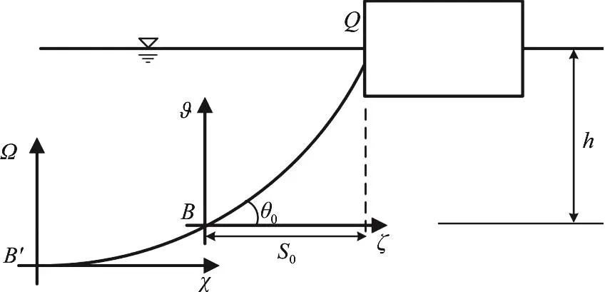
Fig.3 Coordinates of mooring line
In the coordinate system (χ,)Ω, the initial horizontal and vertical tensions of the catenary line can be written as

whereUdenotes the catenary line tension,wis the unit weight of the catenary line,U0denotes the initial horizontal catenary tension.sis the total arc length of the catenary line measured from the point .
The basic catenary line equations are expressed as

Thus the coordinates of the pointsQ,Bin the (χ,)Ωcoordinate system can be written as
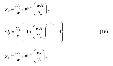

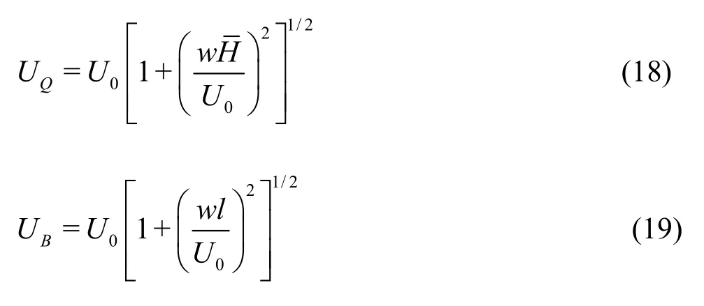
Thus, the linearized stiffness coefficients are

where (XQ,ZQ) are the coordinates of the attachment pointQin the local coordinates as shown in Fig.2.Also the mooring matrix is symmetric, namelyKij=Kji,i=1,2,3,j=1,2,3.
Generally, the lengthHof the mooring line,the projective lengths0and the water depthhare known.The initial horizontal tensionT0, the anchor angle0θand the hypothetical projected lengthlcan be evaluated from Eq.(14) for the catenary line tension and the basic catenary line Eqs.(15).Thus, the mooring stiffness matrix can be calculated using Eqs.(20)-(25).The force of the mooring lines on floating modules can be defined as

1.4 Network model of floating airport
In what follows, the network model of the multi-module floating airport is developed by the integration of above derived models.For a head wave propagating along the huge size of the floating airport,the wave forces on the adjacent modules will have a phase difference, and the wave forces on thei-th module can be expressed as

whereiφdenotes the initial phase angle of thei-th module and we have the relationship
For the modules of the floating airport with a particular spatial distribution, we first introduce a connection topology matrixΦ∈RN×Nwhere its elementijΦis set to 1 if thei-th module is connected with thej-th module, otherwiseijΦis set to zero.Considering the possibility that thei-th module may connect with a number of adjacent modules, according to the mechanical model Eq.(14)of a connector, the total connector forces on thei-th module can be expressed as

Introducing the topology matrix into the dynamics model, one can take the advantages of the network theory to deal with the connection of the network structures of arbitrary topology by only changing the element assignment.It is worth noting that for different types of topology network, such as that of a ring form or a rectangular form, we can formulate the models simply by assigning the element values of the topology matrix accordingly.
Considering the constrained forces of the mooring system on the floating airport, we rewrite the mooring force on thei-th module

whereδ(i,j) is the Delta function andi0indicates the number of modules of the mooring system.
For the network model of serially connected floating airport, based on the single module governing Eq.(1), the wave force model (29), the mechanical model of the connector force (30) and the model of the mooring system (31), the governing equations of the floating airport withNmodules can be written in a standard form as


where the last term represents the mechanical features of the connector among the modules.The parameterεdenotes the coupling strength, physically representing the stiffnesskcof the connector.G(Xi,Xj) is referred as the coupling function in the network theory which defines the specific interaction between thei-th module and thej-th module in all degrees of freedom,expressed by

The coupling function here basically describes the nonlinear geometric relationship for the connectors.

Fig.4 Configuration of 5-module floating airport
By now, a standard procedure for establishing the network model of a floating airport is demonstrated.It should be noted that the modeling method is not only suitable for the floating airport but also for other engineering problems with a similar network structure.
2.Nonlinear dynamic characteristics of a chaintype floating airport
2.1 Simulation parameters
In this paper, a chain-type floating airport consisting of five modules of the same size coupled by parallelized connectors is chosen for the simulation model, as shown in Fig.4.For the chain-type network model of the floating airport, the topology matrixijΦis symmetric, given by

The rigid box-type module is considered and its dimensional data are listed in Table1.The parameters for the wave include the wave heighta=2m,namely 4 times of that in the sea state, and the wave period 9-20 s, which can cover the wave spectrum range of the general sea state.The water depth ish=50m .
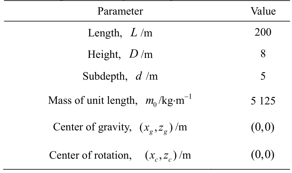
Table1 Properties of single floating structure
In this paper, we consider the mooring condition with the catenary mooring lines symmetrically attached to the head and the tail of the chain-topology floating structure.The parameters for the mooring system include the unit weight of the catenary linew= 332kgf , the lengthH=350m, the projective lengths0=310m and the coordination of the attachment points (XQ,ZQ)=(±100,0).The initial length of the connector isδ=5m, the vertical distance between parallel connectors isδ2=5m.
2.2 Dynamic responses and connector forces
The governingEq.(32)forthefloatingairport involves a geometric nonlinearity due to the coupling effect of the connectors and the system naturally exhibits nonlinear characteristics which are not well investigated by the existing methods.In what follows,the dynamics responses and the connector force will be numerically calculated by using the algorithm of ode15s in the Matlab.

Fig.5 (Color online) The response amplitude versus connector stiffness (T =10s)
Figures 5(a)-5 (c) show the response amplitude of each module in alldegrees of freedom where the con-nector stiffness varies at a fixed wave periodT=10s .Ax,Az,Aβindicate the response amplitudes of surge, heave and pitch motions respectively.It can be seen that the connector stiffness has a great effect on all three motions, which is different from the results of Loukogeorgaki et al.[21], where one sees only the effect on the heave motion.The surge motion(Fig.5(a)) is larger than the heave (Fig.5(b)) and pitch (Fig.5(c)) motions because of the head wave excitation.The motions in each degree of freedom for different modules are similar in terms of oscillation patterns.It is easy to see that all responses suddenly change to large motions at the same time when the connector stiffness is in the range of.Meanwhile, the large motion is accompanied with disorder points and segment lines, which means that the system stays in chaotic or high order harmonic motion patterns, as consistent with the observation made in our previous work[13].To view various motion patterns, two time series for the surge motion of the second module are shown in Fig.5(d), at two typical settings of connector stiffness, respectively.The upper chart shows the harmonic motion in a weak oscillation state and the lower chart shows the chaotic motion in a large oscillation state.Due to the synergic effect, the motion patterns of other time series of responses in different degrees of freedom are similar,which are not shown here.In addition, the responses from a small oscillation jumping to a large motion is in a sudden manner and the variation of such magnification of the amplitude can reach 24 times in the surge motion, 8 times in the heave motion and 6 times in the pitch motion.In addition, the range of the stiffness for the large amplitude motion appears differently from that of the slender peaks of resonance of linear systems.
In order to reveal the response evolution under the wave period, three typical stiffnesses of105N/m are chosen where the first two are in the large motion range and the last one is in the weak oscillation state, and the amplitude frequency characteristic curves are plotted for the first module,as shown in Fig.6.Due to the similarity among responses of different modules shown in Fig.5, curves of other modules are not shown here.Figure 6(a)indicates that the connector stiffness plays an important role in the surge motion.There are some resonance peaks in the frequency range we choose.For different connector stiffnesses, the number and the positions of resonance peaks change largely.With the increase of the connector stiffness, the surge oscillation in the high frequency is suppressed.From the heave motion shown in Fig.6(b), one sees that there are two dominant resonance peaks and the connector stiffness ofkc=1.54×10⁵N/m seems liable to cause shape changes.The pitch motion is insensitive to the changes of the connector stiffness, as shown in Fig.6(c).There are several resonance peaks.The dominant resonance peak is located in the interval of 0.409rad/s <ω< 0 .551rad/s , and the maximum response amplitude isβ1=0.12rad.

Fig.6 (Color online)The amplitude-frequency curves for the first module
Next, the connector forces are analyzed.Figure 7 illustrates the connector forces against the connector stiffness.The connector forces see a similar evolution as the responses.All connectors’ forces see a similar trend in the variation in the range of the connector stiffness and a pair of connectors’ forces between the adjacent modules are identical as shown in Figs.7(a),7(b).There are two dominant peaks.The connector forces are large when the modules involve large motions.The maximum connector forces happen at the stiffnesskc=1.855×10⁵N/m , and they suddenly drop down when the stiffness is further increased.Figure 8 shows the connector forces against the wave frequency.There are three distinct load peaks and the maximum load peak locates in the range of 0.415rad/s <ω< 0 .557rad/s .When examining the amplitude frequency curves shown in Fig.6, we find that the region of the maximum load peak coincides with the resonance interval of the pitch motion, which implies that the pitch motion has a significant influence on the connector force.

Fig.7 (Color online) Connector force evolutions against the connector stiffness (T =10s)
2.3 Stability analysis of floating airport based on amplitude death phenomena
The term of the amplitude death typically means the oscillation cease of coupled oscillators in autonomous networks[22], which was first observed by Bar-Eli[23]in coupled chemical oscillators.Resmi et al.[14]extended the concept of the amplitude death to the special behavior of oscillation suppression in nonautonomous networks.Here we use Resmi’s definition of the amplitude death to describe the special phenomenon of the weakened oscillatory behavior of the floating airport.Unlike the traditional stability analysis, we study the dynamic stability of the floating airport based on the amplitude death mechanism.The very large floating airport on sea is a typical nonautonomous system which could involve a very weak oscillation state due to nonlinear coupling effect between adjacent modules.Since the weak oscillation state may lead to small connection loads and small deformation of the platform, as is important for the safety design of the floating airport.

Fig.8 (Color online) Connector force versus wave angular frequency
As seen from the response amplitude curves in Fig.5, there are two jumping up and two dropping down cases and all modules’ oscillation amplitudes in the three degrees of freedom maintain in a small oscillation state in the three intervals ofc<6.1×kand.The weak oscillation state is induced by the coupling effect of the network,referred as to the amplitude death (AD) phenomenon[14].The jumping up or dropping down phenomenon happens simultaneously among all the modules in all degrees of freedom due to the network synergistic effect.The response corresponding to the weak oscillation states is a harmonic motion with the oscillation period coinciding with the wave period exactly[13].Under a certain condition[12], the coupling effect of the connectors will force the dynamics of all modules in the floating airport to converge to a weak oscillation state collectively.The amplitude death comes into being due to the fact that there are different solution branches for a nonlinear network and when the steady state of the network falls into a weak oscillation solution branch.The distribution of the amplitude death state in the design parametric regions is a very much concerned issue because it may provide a valuable guidance for the stability and safety design of the system.
Next, the AD region of the floating airport will be studied in the parametric domains of the wave period and the connector stiffness.Because of the network synergistic effect that the responses of all modules in all degrees of freedom have the same oscillation patterns, the AD behavior of the surge motion of the first module can represent the AD behaviors of others.By scanning point by point in a two dimensional parameter domain where abscissa indicates the wave period and the vertical scale indicates the connector stiffness, the AD distribution region can be obtained.

Fig.9 (Color online) Parameter domains (kc,T) for amplitude death for wave height a=2m where the regions labeled as “AD” correspond to weak oscillatory states and the regions labeled as “Others” indicates large oscillation state
Figure 9 illustrates the amplitude death domain of the multi-module floating airport in the parameter space (kc,T).In Fig.9, the region marked with red color denotes the large motion state that corresponds to high harmonic or chaotic motions and the white area indicates the parameter space for the AD state which corresponds to small oscillatory motions of the floating airport.On the boundary between the white and red regions, the responses of all modules will have a step change and the boundary is quite irregular.At a glance of the graph globally, we find that the AD domain distributes mainly in left and right sides separated by shapes of a long-and-bended stripe,peninsula and islands.Only when the parameters are located in the white domain, the multi-module floating airport will be in the weak oscillation state and the loads of the flexible connectors will be suppressed to a low level.The red area is in the middle of the parameter domain, which indicates that the AD state cannot be expected under the wave condition about 12s ≤T≤ 1 5 s no matter what the connector stiffness is.This band of wave periods leads to large responses of the floating airport and the connector forces.This feature coincides with the amplitude frequency characteristics in the region 0.409rad/s<ω<0.551rad/s in Fig.6(c).When further examining the configuration of the connectors between the adjacent modules, we find that the connection forms a four linkage mechanism, that can not restrict the pitch motion well.Thus we believe that the four linkage connection mechanism may be the cause of the high-rise responses in the red parametric domain.
Figure 10 shows the contour diagram of the connector force for theconnector.It provides a visual atlas to view the distribution of the low lever connector force colored in blue.The distribution chart of the connector loads coincides with the chart of the amplitude death shown in Fig.9.Large responses always lead to large connector loads.

Fig.10 (Color online) Contour diagram of connector force for connector

Fig.11 (Color online) Parameter domains of amplitude death in space (kc,T) for wave height a=1m where the regions labeled as “AD” correspond to weak oscillatory states and the regions labeled as “Others” indicates large oscillation state
It can be concluded that the following features are in common.Number one, the connector configuration and the pitch motion have an important effect on the stability of the floating airport.Number two, the amplitude death map can provide an intuitive and simple reference for the stability design of the floating airport and has an important value in engineering applications.Although the AD domain shown in Fig.9 can provide theoretical guideline for the connectors,the sea condition may constantly change, so it is interesting to see the change of the AD region as the wave condition changes.Figure 11 plots the AD distribution chart for the wave heighta=1m in the similar way of illustration where the white region denotes the AD state and the red domain indicates the large oscillation state.Compared with Fig.9, we find that the amplitude death domain expands greatly with the decrease of the wave height.It is important to note that for the wave height, the AD domain is no longer separated and becomes a connected region.It means that the AD state for the floating airport can always be expected for any wave period if we can adjust the connector stiffness suitably for the wave heighta= 1m .
Notice that the governing Eq.(32) of the floating airport characterizes a generalized chain-formed network which allows an arbitrary number of modules in the system.It was remarked that the number of modules may have a great effect on the connector loads and responses[7].From the perspective of the network dynamics, the number of isolators could also play an important role for the onset of the amplitude death[12,24-25].Here, we provide another two examples forN=2,4 with the total length of the floating structure the same as the 5 module floating airport model.Figure 12 illustrates the surge motion amplitude of the first module with the respect to the connector stiffness for the three typical models with the wave periodT=10s.

Fig.12 (Color online) The surge response amplitudes of the first module versus connector stiffness for different numbers of float modules (T=10s)
In Fig.12, for the floating airport with two modules, the response (black solid line) is always weak in the range of the connector stiffness except the small resonance peak at the connector stiffnesskc=5.000×10⁵N/m .For the 4-module floating air-port, the response (blue dash line) is quite similar to the case of the 5-module’s.There are also two regions of large oscillation states.When examining the domain of large amplitude carefully, we find that the bandwidth of 5-module case is larger than that of 4-module case and the maximum amplitude is magnified.In other words, the amplitude death domain decreases with the increase of module numbers due to the coupling effect.Thus, the use of less modules for the same scale of the floating structure can reduce the response amplitude such as shown by the example of 2-module case in Fig.12.Of course, a longer floating body leads to a larger internal force in the floating module[26].On the other hand, the AD domain decreases for the floating structure with a large number of modules.So for practical engineering problems, we have to balance the advantages and disadvantages of the number of the modules at the same time.
3.Conclusion
The present paper presents a dynamic model of single floating module based on the linear wave theory, where the hydrodynamic coefficient is formulated by the eigen-function expansion method.An elastic hinged compliant connector is proposed and its mechanics model is developed with a geometric nonlinearity.With a classical mooring system model for the catenary line, a generalized chain-typed nonlinear network dynamics model for a floating airport is built by integrating the individual models based on the structure topology.The numerical results of the dynamic response and the connector load reveal that the nonlinearity of the connector plays an important role in the dynamics behaviors of the system.Unlike linear systems, the response and the connector load see sudden jumping phenomena due to the geometric nonlinearity.In addition, the amplitude death phenomenon, a weak oscillatory state, is studied and the mechanism of the amplitude death phenomenon is elaborated.The parametric domain for the amplitude death state is numerically studied in a span of connector stiffness and wave period.The effect of the wave height on the distribution of the amplitude death state is also studied.Further, the effect of the module number for the same scale of the floating airport is analyzed together with a discussion on the amplitude death phenomenon.In short, the paper presents a network modeling approach for multimodule floating structures, illustrates the effects of nonlinearity on system dynamics, and introduces a new concept of amplitude death for the global dynamic stability, which is very important for the safety design of floating airport.Finally, the methodology is applicable to any engineering problems with a similar network structure.
- 水動力學(xué)研究與進(jìn)展 B輯的其它文章
- Call For Papers The 3rd International Symposium of Cavitation and Multiphase Flow
- Two-phase SPH simulation of vertical water entry of a two-dimensional structure *
- A selected review of vortex identification methods with applications *
- Tracer advection in an idealised river bend with groynes *
- Simulation of the overtaking maneuver between two ships using the non-linear maneuvering model *
- The effect of downstream resistance on flow diverter treatment of a cerebral aneurysm at a bifurcation: A joint computational-experimental study *

