Strain rate and cold rolling dependence of tensile strength and ductility in high nitrogen nickel-free austenitic stainless steel?
Gui-Xun Sun(孫貴訓(xùn)),Yue Jiang(江月),Xiao-Ru Zhang(張曉茹),Shi-Cheng Sun(孫世成), Zhong-Hao Jiang(江忠浩),?,Wen-Quan Wang(王文權(quán)),?,Jian-She Lian(連建設(shè))
1 Key Laboratory of Automobile Materials,College of Materials Science and Engineering,Jilin University,Changchun 130025,China
2 Key Laboratory of Advanced Structural Materials,Ministry of Education,College of Materials Science and Engineering, Changchun University of Technology,Changchun 1130012,China
Strain rate and cold rolling dependence of tensile strength and ductility in high nitrogen nickel-free austenitic stainless steel?
Gui-Xun Sun(孫貴訓(xùn))1,Yue Jiang(江月)1,Xiao-Ru Zhang(張曉茹)1,Shi-Cheng Sun(孫世成)2, Zhong-Hao Jiang(江忠浩)1,?,Wen-Quan Wang(王文權(quán))1,?,Jian-She Lian(連建設(shè))1
1 Key Laboratory of Automobile Materials,College of Materials Science and Engineering,Jilin University,Changchun 130025,China
2 Key Laboratory of Advanced Structural Materials,Ministry of Education,College of Materials Science and Engineering, Changchun University of Technology,Changchun 1130012,China
The tensile strength and ductility of a high nitrogen nickel-free austenitic stainless steel with solution and cold rolling treatment were investigated by performing tensile tests at different strain rates and at room temperature.The tensile tests demonstrated that this steel exhibits a significant strain rate and cold rolling dependence of the tensile strength and ductility. With the increase of the strain rate from 10?4s?1to 1 s?1,the yield strength and ultimate tensile strength increase and the uniform elongation and total elongation decrease.The analysis of the double logarithmic stress–strain curves showed that this steel exhibits a two-stage strain hardening behavior,which can be well examined and analyzed by using the Ludwigson equation.The strain hardening exponents at low and high strain regions(n2and n1)and the transition strain(εL)decrease with increasing strain rate and the increase of cold rolling RA.Based on the analysis results of the stress–strain curves,the transmission electron microscopy characterization of the micro structure and the scanning electron microscopy observation of the deformation surfaces,the significant strain rate and cold rolling dependence of the strength and ductility of this steel were discussed and connected with the variation in the work hardening and dislocation activity with strain rate and cold rolling.
high nitrogen nickel-free austenitic stainless steel,cold rolling,Ludwigson equation,tensile strength and ductility
1.Introduction
High nitrogen nickel-free austenitic stainless steels(nitrogen concentration is usually higher than~0.4%in mass percent,termed as HNSs)have been studied extensively for their unique mechanical properties,i.e.,improved strength and ductility,adequate work hardening ability,high fracture toughness and desirable resistance to corrosion,etc.[1–11]These attractive properties depend on the benefit roles of nitrogen in enhancing solid-solution strengthening and stabilizing austenitic structure.[1,3–6,8]The high potential of nitrogen to stabilize austenitic structure would make the expensive nickel be replaced and offer an additional advantage of cost-saving.[1,3,4,6,8]Moreover,the enhanced solubility of nitrogen with the increase of the contents of alloying elements, i.e.,manganese and chromium,can be advantageous for it to be effectively applied in the manganese and chromium-based stainless steels.[1,3,8]
Extensive researches focused on the tensile mechanical properties and the microstructure evolution of the HNSs or other nitrogen alloyed austenitic stainless steels for extending their engineering applications have been reported.[12–31]In these studies,the effects of various kinds of internal and external factors,such as grain size,[12,16]twin structure(e.g., size,shape,and amount of twin),[17,23–25]alloying elements (e.g.,contents of carbon and nitrogen)[13–15,21,26,30,31]and testing temperature and strain rate[18–20,22,27–29]on the plastic deformation behaviors have been investigated extensively.Nevertheless,it is noted from these studies that very limited efforts were made to study the strain rate and cold rolling dependence of tensile strength and ductility of the HNS at a very wide range of strain rate and cold rolling deformation.
In this paper,the HNSs with a variety of initial microstructure and a very wide range of the strength and ductility were obtained through solution and cold rolling treatments.The corresponding tensile strength and ductility are investigated by performing tensile tests under a wide strain rate ranging from 10?4s?1to 1 s?1at room temperature.The experimental tensile stress–strain curves were then examined by using the Ludwigson equation.Based on the experimental results of the stress–strain curve,the transmission electron microscopy observation of the microstructure and the scanning electron microscopy characterization of the deformation surfaces of this HNS,the significant strain rate and cold rolling dependence of the strength and ductility and the underlying plastic deformation mechanism was discussed and connectedwith the variation in the dislocation activity with strain rate and cold rolling.
2.Theoretical background
The investigations on the metals and alloys have attracted extensive attention in the past years because of their good performance.[32–39]For the purpose of optimizing the microstructure and mechanical properties of the metals and alloys and extending their practical applications,it is of particular importance to analyze their plastic deformation behavior or stress–strain curves.One of the earliest attempts is the empirical mathematical equation proposed by Hollomon(termed as the Hollomon equation).[40]As well as the simplicity of the Hollomon equation,it can also explain the underlying deformation mechanisms and provide the correlation of the involved parameters with the microstructure features.Thus,this equation has been quite common to analyze the plastic deformation behavior of the polycrystalline metals during the monotonic tensile/compressive deformation over the decades. Based on the true stress-true plastic strain(σ–ε)curves,the Hollomon equation can be given by

where K and n are strength coefficient and strain hardening exponent respectively.[40–42]However,it is found that the plastic deformation behavior of some face centered cubic metals and alloys with low stacking fault energy,i.e.,austenitic stainless steels,cannot be adequately analyzed by this equation due to the existing stress deviation at low strain region.[43–45]A modified Hollomon equation was thus proposed by Ludwigson(termed as the Ludwigson equation)for giving an explanation on this stress deviation appropriately,[43]which is given by

where K1and n1have the same meanings as K and n in Eq.(1), exp(K2+n2ε)is the term related to the stress deviation from the Hollomon equation at low strain region,exp(K2)corresponds to the onset of the macroscopic plastic deformation, i.e.,the value of σ at ε=0,and n2is the strain hardening exponent at low strain region.[46–48]Besides K1,n1,K2,and n2in the Ludwigson equation,the transition strain(εL),i.e.,the minimum strain above which the stress–strain curve can be well fitted by the term K1εn1,is also an important parameter. It represents a critical strain across which a transition in plastic deformation mechanism from planar slip of dislocations to the multiple slip of dislocations occurs as the plastic deformation proceeds.It has been demonstrated in previous literature that the stress deviation at ε<εLmainly results from the shor-trange resistance caused by the pinning of carbon and nitrogen interstitial atoms on planar gliding dislocations,while the strain hardening at ε>εLmainly arises from the long-range stress induced by the interactions of dislocations on intersecting slip systems.[42,43,49,50]
3.Experimental
In this study,the as-received HNS bar with a diameter of about 30 mm was first solution treated at 1150°C for 8 hours followed by water quenching to form a uniform initial austenitic structure,and then it was cold rolled on a laboratory two-high mill at room temperature.The total reduction of area (RA)was about 10%,30%,and 50%,respectively.The corresponding nominal chemical compositions have been reported in Ref.[51].Uniaxial tensile tests(at least three times for each strain rate)were performed at room temperature on a MTS-810 test system with a broad strain rate ranging from 10?4s?1to 1 s?1.Dog-bone shaped specimens for tensile tests with a size of 8 mm×2 mm×1 mm(length×width×thickness)in the gauge section were cut from the HNS sheets with solution treatment and cold rolling condition by using an electrod is charging machine.Then these specimens were prepared by careful mechanically grinding and polishing to achieve a test surface with mirror-like finish.
Microstructure observation of the present HNS before testing was performed by field emission scanning electron microscopy(FESEM,SUPRA-40)with electron backscattering diffraction(EBSD)analysis.The obtained data for EBSD mapping were analyzed with a discrete step size in the range of 10–100 nm by using orientation imaging microscopy.Crystallographic structure of the present HNS before testing was examined by x-ray diffraction analysis(D/max 2500 PC)with Cu Ka radiation.Microstructure characterization of the present HNS before and after testing was carried out on a transmission electron microscopy(TEM,JEM-2100F)under an accelerating voltage of 200 kV respectively.To obtain the thin foil HNS for EBSD and TEM observation,the specimens cut from the bulk HNS were first mechanically ground to a thickness of~20μm,then thinned by an ion beam with a tilt angle of 4°–8°using an Ion Polishing System(Gantan 691,USA)under a voltage of 5 kV.Morphologies of the deformation surfaces of the present HNS were examined by FESEM observation.
4.Results
4.1.Microstructure and phase structure
Figure 1 shows the inverse pole figure(IPF)maps of the present HNS.As shown,the colors displayed in the superimposed stereographic triangle(the inset in Fig.1(a))reveal the corresponding variations of the crystallographic orientations on the observed surface.It is clearly seen that the present HNS exhibits roughly equiaxed grains with random crystalline orientations.The twins emerge in some large-sized grains.As RA increases,the microstructure of the present HNS is significantly refined and becomes in homogenous.The grain size cannot be clearly identified in some local regions,especially for those with cold rolling RA being larger than 30%(note that the magnifications of these IPF maps are different).
Figure 2 shows the typical TEM bright-field images of the present HNS.When cold rolling RA is0%(the solution treated HNS,Fig.2(a)),the thick annealing twins can be observed in some grains.When cold rolling RA is 10%(Fig.2(b)),many straight stacking faults(SFs)with parallel interfaces can be observed.Some dislocation structures can also be seen between these SFs.When cold rolling RA increases to 30% (Fig.2(c)),many mechanical or deformation twins emerge. The thickness of these twins becomes finer(in the nanometer scale)and the length becomes shorter(in the micrometer scale).When cold rolling RA increases to 50%(Fig.2(d)),the secondary deformation twins form and the thickness of twins becomes much finer.These newly formed twins intersect with the primary twins from different crystallographic orientations, which seems to originate from the cutting of the primary twins. The interior angle between the intersection of primary and secondary twin is about 70°,which has been reported in the previous paper.[52]

Fig.1.(color online)Inverse pole figure(IPF)maps of the present HNS with cold rolling RA of(a)0%,(b)10%,(c)30%,(d)50%.

Fig.2.TEM bright-field image of the present HNS with cold rolling RA of(a)0%,(b)10%,(c)30%,(d)50%.
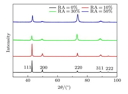
Fig.3.(color online)x-ray diffraction pattern of the present HNS.
Figure 3 shows the x-ray diffraction patterns of the present HNS.It reveals that the present HNS is only composed of the fcc austenitic phase without preferred orientations.No characteristic peaks of ferrite and martensite phases can be observed.The absence of the martensite phase in the present HNS indicates that the phenomenon of the deformation induced austenite–martensite transformation as commonly observed in other austenitic stainless steels did not substantially take place in the present HNS.In addition,the enhanced diffraction peak broadening at high cold rolling RA indicates that the grain or twin structures have been significantly refined.
4.2.Tensile strength and ductility
Figure 4 shows the engineering stress–strain curves of the present HNS deformed under uniaxial tensile tests with different strain rates(10?4s?1to 1 s?1).As seen,the tensile stress initially increases almost proportionally with the strain in the elastic deformation region.As strain further increases, a continuous yielding and strain hardening behavior is clearly observed on the tensile curves.The region of strain hardening gradually becomes short with the increase of strain rate or cold rolling RA.It is also seen from Fig.4 that the variations of the yield strength and ultimate tensile strength of the present HNS reflect a continuous increase trend with the increase of strain rate or cold rolling RA.In contrast,the variations of the uniform elongation and total elongation reflect a continuous decrease trend with increasing strain rate or cold rolling RA.
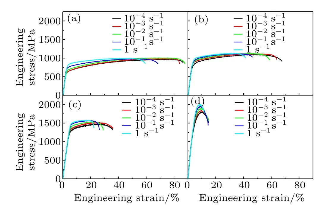
Fig.4.(color online)Engineering stress–strain curves of the present HNS with cold rolling RA of(a)0%,(b)10%,(c)30%,(d)50%.
4.3.Analysis of stress–strain behavior
Figure 5 shows the typical logσ–logε curves and the corresponding ln(σ?K1εn1)?ε curves of the present HNS with cold rolling RA of 0%and 50%deformed under a strain rate of 10?2s?1.In these logσ–logε curves,a distinct two-stage hardening behavior with a gradual transition can be observed,i.e.,logσ initially increases slowly in a nonlinear way up to a certain strain(or logε)and then increases relatively rapidly in a linear way.Such two-stage strain hardening behavior is similar to those observed in previous studies,[42,47–49,53]indicating that the Ludwigson equation (Eq.(2))can be used to analyze the plastic deformation behavior of the present HNS.Various parameters in the Ludwig-son equation(Eq.(2))can be determined by using the analysis method of Ludwigson.[43]By fitting the experimental logσ–logε data at high strain region,the values of K1and n1were obtained.Then the values of K2and n2were determined by fitting the experimental ln(σ?K1εn1)?ε data at low strain region(Figs.5(b)and 5(d))by using the obtained values of K1and n1.The value of εLcan be determined by letting the value of exp(K2+n2εL)be very small in comparison with the value ofi.e.,setting r=exp(K2+n2εL)/to be some arbitrary small value.[42,43,49,50,53,54]Based on the previous studies,[42,43,49,50,53,54]a value of r=0.01 is selected to determine the value of εLin this study.The resultant data of K1,n1,K2,and n2obtained by the above analysis are listed in Table 1.The corresponding variations of n1,εL,and n2of the present HNS with strain rate and cold rolling condition are shown in Fig.6.It can be seen that the values of n1,εL, and n2tend to decrease with the increase of strain rate and the increase of cold rolling RA.Figure 7 shows the typical comparison results of experimental and the corresponding fitted σ–ε curves of the present HNS deformed under a strain rate of 10?2s?1.As seen,the experimental σ–ε curves at the entire strain range can be well fitted by using the Ludwigson equation.
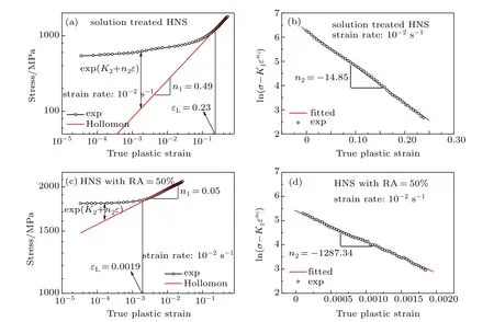
Fig.5.(color online)Typical double logarithmic σ–ε curves and the corresponding ln(σ?K1εn1)?ε curves of the present HNS with cold rolling RA of 0%and 50%deformed under a strain rate of 10?2 s?1.
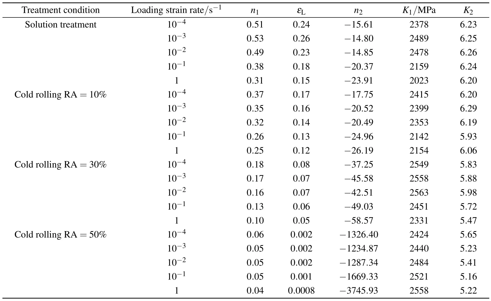
Table 1.Parameters derived by using the Ludwigson equation from the stress–strain curves of the present HNS.
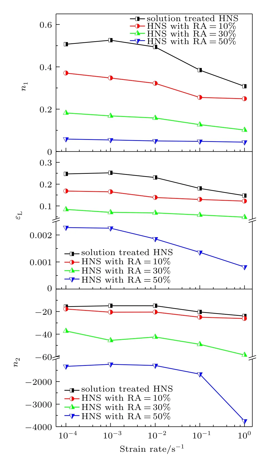
Fig.6.(color online)Variations of the parameters(n1,εL,and n2)with strain rate of the present HNS derived by using the Ludwigson equation.
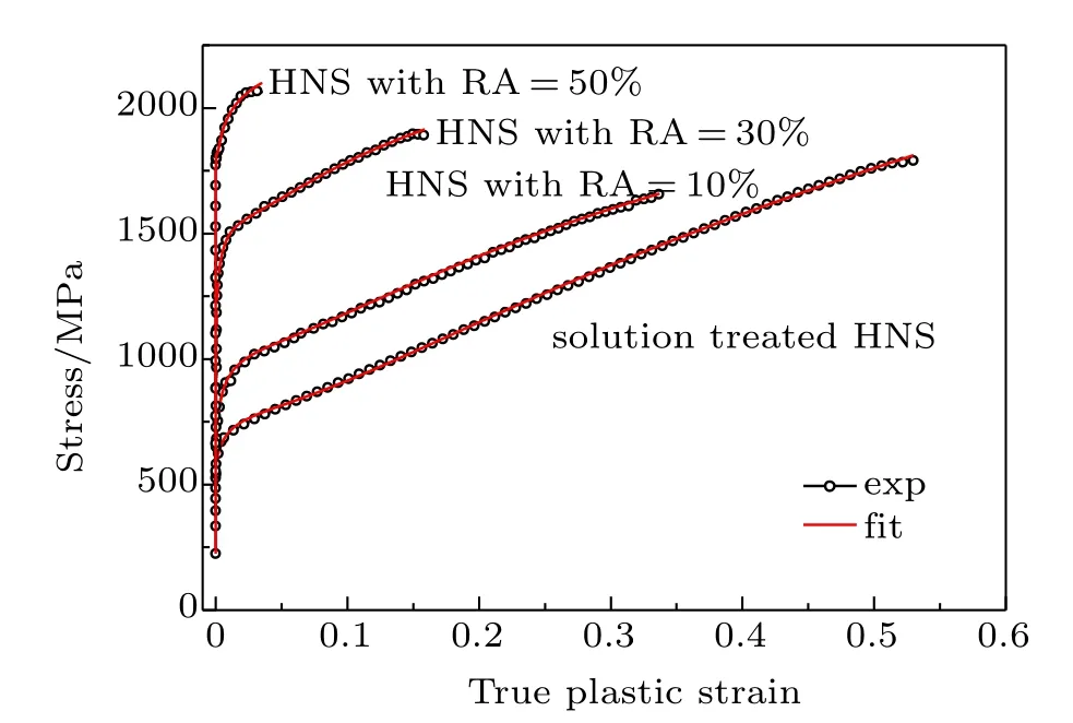
Fig.7.(coloronline)Typical comparisons of experimental and fittedσ–ε curves of the present HNS deformed under a strain rate of 10?2 s?1.
4.4.Microstructures of the deformed specimens
Figure 8 shows the typical TEM images of the dislocation structures of the solution treated HNS at different strains and strain rates(10?4s?1and 1 s?1).At low strain,i.e.,the true plastic strain is about 6%(Figs.8(a)and 8(d)),the randomly distributed dislocations can be observed and the density of these dislocations increases with increasing strain rate.At high strain,i.e.,the true plastic strain is about 35%(Figs.8(b) and 8(e)),the density of tangled dislocations becomes higher and the distribution of the dislocations appears more uniform. The details of the dislocations at high strain can be seen in the high-resolution TEM images(Figs.8(c)and 8(f)),which correspond to the regions marked by white arrows in Figs.8(b) and 8(e).
Figure 9 shows the typical TEM images of the dislocation structures of the present HNS with cold rolling RA of 50%at different strains and strain rates(10?4s?1and 1 s?1). As shown,the density of dislocations becomes higher even at low strain,i.e.,the true plastic strain is about 0.5%(Figs.9(a) and 9(e)),compared with that in the solution treated HNS at low strain.At high strain,i.e.,the true plastic strain is about 3%(Figs.9(c)and 9(g)),the density or number of the dislocations becomes higher than that at low strain.The details of the dislocations at low strain and at high strain can be seen in the high-resolution TEM images(Figs.9(b)and 9(f),Figs.9(d) and 9(h)),which correspond to the regions marked by white arrows in Figs.9(a)and 9(e)and Figs.9(c)and 9(g).
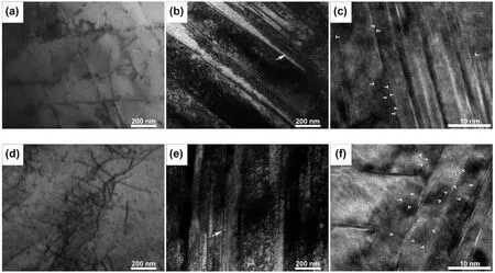
Fig.8.TEM images of the solution treated HNS deformed under different true plastic strains of 6%(a),(d)and 35%(b),(e)and the corresponding high-resolution TEM images with different strain rates:((a),(b),(c))10?4 s?1,((d),(e),(f))1 s?1.
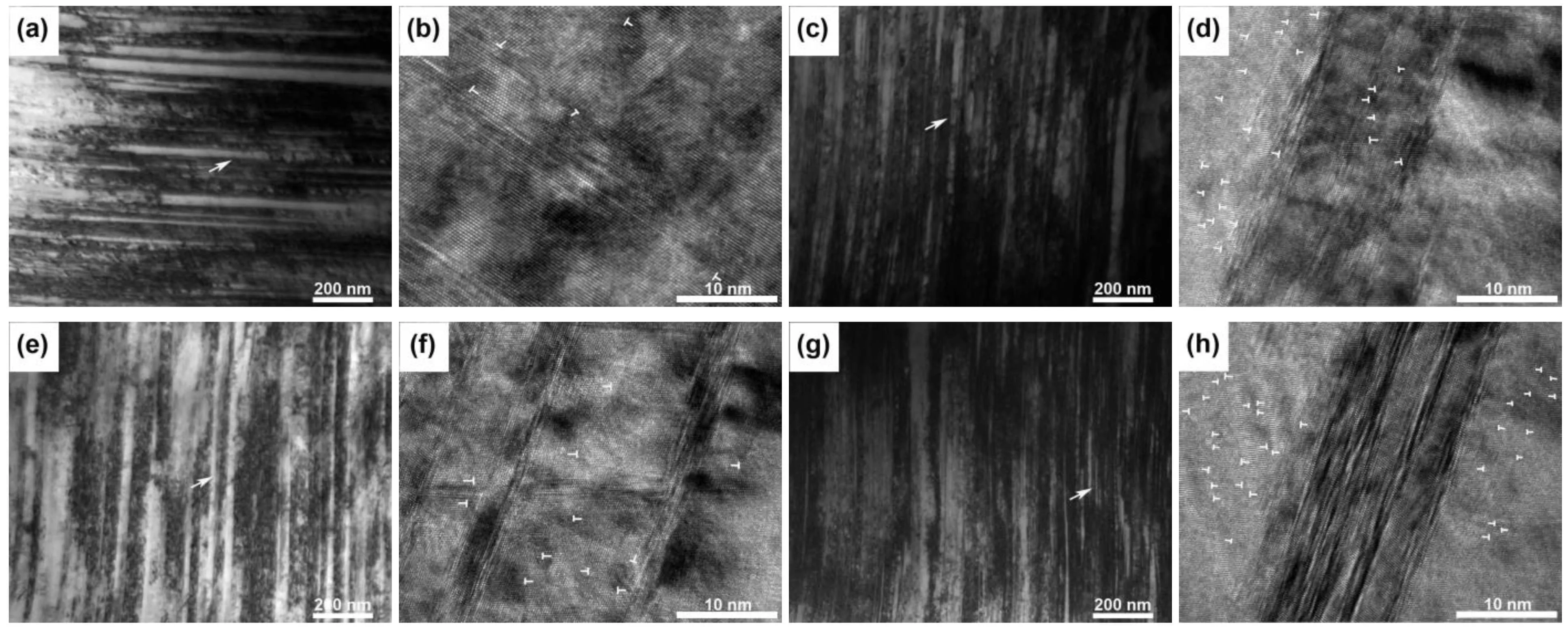
Fig.9.TEM images of the present HNS with cold rolling RA of 50%deformed under different true plastic strains of 0.5%(a),(e)and 3%(c),(g)and the corresponding high-resolution TEM images with different strain rates:(a)–(d)10?4 s?1,(e)–(h)1 s?1.
4.5.Morphologies of deformation surfaces
Figure 10 shows the typical FESEM images of the deformation surface morphologies taken at the necking region of the present HNS deformed under two different strain rates (10?4s?1and 1 s?1).As shown,the fracture surface is almost perpendicular to the tensile axis.The deformation surfaces are obviously uneven and/or corrugated,displaying typical normal fracture feature.The roughness of the deformation surface decreases with the increase of strain rate and the increase of cold rolling RA.On the deformation surfaces of the solution treated HNS,the local shear units with different sizes and shapes can be seen,indicating that the shear localization process has occurred.The amount of these local shear units decreases with increasing cold rolling RA.In addition,the plenty of deformation or shear bands(marked by red arrows)can be seen on the deformation surface of the present HNS.These shear bands appear in groups and are approximately parallel to one another. Such deformation mode through shear bands indicated that the localized plastic deformation or instability is usually prevalent at large plastic strain,i.e.,the necking region.With increas-ing strain rate and cold rolling RA,the shear bands become straight and long rather than the curved and short shear bands observed at low strain rate and small cold rolling RA.Moreover,the microvoids or microcracks can be also seen.The size of these microcracks becomes large and their number or density becomes small as strain rate increases or cold rolling RA increases,indicating a high tendency of cracking.
These above morphologies of the deformation surfaces are in agreement with the observations of the tensile strength and ductility shown in Fig.4,which also give the direct explanation for the strain rate and cold rolling dependence of the tensile strength and ductility of the present HNS.
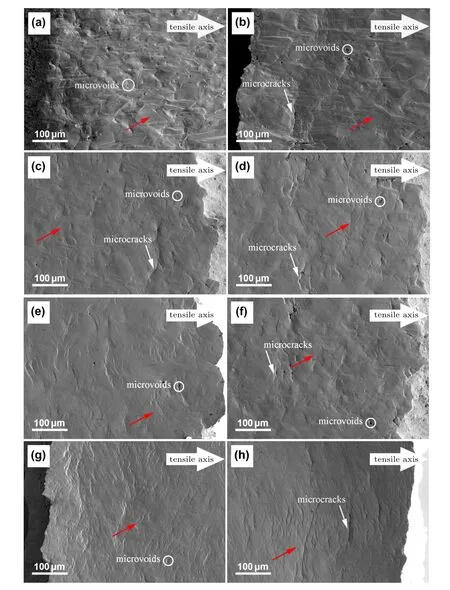
Fig.10.(color online)FESEM images of the deformation surfaces taken at the necking region of the present HNS with cold rolling RA of 0%((a),(b)),10%((c),(d)),30%((e),(f)),50%((g),(h))deformed under two different strain rates:((a),(c),(e),(g))10?4 s?1, ((b),(d),(f),(h))1 s?1.
5.Discussion
In polycrystalline metals,the statistically stored dislocations(SSDs)would generate initially in intragranular sources during the plastic deformation process.The glide of the SSDs is gradually in a form of planar or single slip and tends to distribute uniformly in the grain interiors.[55,56]This glide of SSDs would undergo short-range resistance due to the local pinning of carbon and nitrogen interstitial atoms.[49,54]As the deformation proceeds,the geometrically necessary dislocations(GNDs)would generate in the regions near the grain boundaries(GBs)to relax the stress/strain concentration.[55,56]The glide of GNDs transforms gradually into the multiple slip on the intersecting slip systems[55,56]and expands from the GB regions towards to the grain interiors with the increase of strain.The region of the multiple slip becomes larger and that of planar slip becomes smaller and disappears gradually.From different strain hardening roles of the planar slip and the multiple slip,the above dislocation activities can be clearly identifi ed by the strain hardening exponents(n1and n2)and the transition strain(εL)derived from the tensile stress–strain curves by using the Ludwigson equation.It has been suggested that n1is the measurement of the long-range stress associated with the interaction among the dislocations on the intersecting slip systems,n2is the measurement of the short-range stress due to the interactions of planar glide dislocations with solution interstitial atoms(e.g.,carbon and nitrogen),and εLrepresents the strain at which a significant transition in the dislocation glide mode from the planer glide to the cross slip takes place.Therefore,the dependence of the dislocation activities on strain rate and cold rolling RA can be explained through the variations of n1,n2,and εLwith strain rate and cold rolling RA.[49,57,58]
For dislocations to nucleate and emit in intra-granular sources,a critical(threshold)stress is required in the plastic deformation of polycrystalline metals.The subsequent plastic deformation would involve the multiplication and motion of dislocations and the interactions of dislocations on intersecting slip systems.The dislocation network created due to such dislocation activities would further hinder the motion of dislocations,which thus leads to the strain hardening.At high strain rate,owing to the high density or high storage rate of dislocations(SSDs and GNDs)generated initially in intra-granular sources,a high initial critical stress or a high yield strength would be expected.As deformation proceeds,these high density or high storage rate of dislocations would enhance the multiple slip process.As a result,the transition in the dislocation glide mode from the planer glide to the multiple slip would occur at a smaller strain.Meanwhile,the enhanced interaction of dislocations would promote the dynamic recovery process of dislocation structure occur earlier or make the dislocation substructures form earlier(Figs.8(b)and 8(e), Figs.9(c)and 9(g)).Thus,a rapidly reduced strain hardening would occur at high strain rate.In contrast,a slowly reduced strain hardening would be expected at low strain rate.At large cold rolling RA,owing to the significant refinement of the grain or twin structure caused by cold rolling deformation,a high initial critical stress or a high yield strength would also be expected.As deformation proceeds,the reduced grain interior space would limit the initial planar slip process and make the transition in the dislocation glide mode from the planarglide to the multiple slip occurs at a much smaller strain.Meanwhile, the reduced grain interior space at large cold rolling RA would promote the dynamic recovery process of dislocation structure occur earlier or make the dislocation substructures form earlier(Figs.8(b)and 9(c),Figs.8(e)and 9(g)).Hence,a rapidly reduced strain hardening would occur at large cold rolling RA. In contrast,a slowly reduced strain hardening would take place at small cold rolling RA.Such variations in the strain hardening behavior are confirmed by the reduced n1,εL,and n2with increasing strain rate and the increase of cold rolling RA(Table 1 or Fig.6).It can also be connected with the strain rate and cold rolling dependence of the ultimate tensile strength of the present HNS.The increased ultimate tensile strength at high strain rate or large cold rolling RA arises from the higher yield strength in spite of the smaller stress increment caused by the rapidly reduced strain hardening(smaller n1)(Fig.4).
Owing to the inhomogeneous nature of plastic deformation of polycrystalline metals,a high strain hardening ability is generally needed to delay the deformation or strain localization process.[59]At low strain rate,the development of the multiple slip and substructure would be more fully and uniformly over a wide strain range,which suppresses the deformation or strain localization process and delays the onset of plastic instability or necking until a larger strain level.Meanwhile,the grain deformation or GB sliding may also occur at low strain rate,which could delay the nucleation and growth of local microcracks by enhancing the deformation accommodation among the grains.At low strain rate,the strain hardening can continue over a larger strain range,a high tensile ductility (uniform and total elongations)is thus expected.In contrast, at high strain rate,the strain hardening would reduce rapidly as the strain increases.The nucleation and growth of local microcracks will occur at a low strain level,leading to a low tensile ductility at high strain rate.At small cold rolling RA, the development of the multiple slip and substructure would be more fully and uniformly due to the enough interior space, which suppresses the deformation or strain localization process and delays the onset of plastic instability or necking until a higher strain.At small cold rolling RA,the strain hardening can continue over a larger strain range,a high tensile ductility (uniform and total elongations)is thus expected.In contrast, at large cold rolling RA,the strain hardening would reduce rapidly as the strain increases.The nucleation and growth of local microcracks will occur at a low strain level,resulting in a low tensile ductility at large cold rolling RA.The above explanations for the strain rate and cold rolling dependence of the tensile ductility of the present HNS are well supported by the characterization results of the deformation surfaces shown in Fig.10.
6.Conclusions
The tensile strength and ductility of a high nitrogen nickel-free austenitic stainless steel were investigated under tensile tests with a wide strain rate range at room temperature. The tensile tests revealed that this steel shows a strong strain rate and cold rolling dependence of the tensile strength and ductility.The analysis of the double logarithmic stress–strain curves indicated that this steel exhibits a two-stage strain hardening behavior,which can be examined and analyzed by using the Ludwigson equation.Based on the analysis results of the stress–strain curve,the transmission electron microscopy observation of the microstructure and the scanning electron microscopy characterization of the deformation surfaces,the strong strain rate and cold rolling dependence of the tensile strength and ductility of this steel was discussed and connected with the variation in the dislocation activities with strain rate and cold rolling.It reveals that the increased yield strength with the increase of strain rate and increasing cold rolling RA arises from the high density or high storage rate of dislocations generated at high strain rate and the reduced interior space caused by large cold rolling deformation,the increased ultimate tensile strength with the increase of strain rate and the increase of cold rolling RA arises mainly from the higher yielding before lower strain hardening ability(rapidly reduced strain hardening),the decreased uniform and total elongations with increasing strain rate and increasing cold rolling RA are attributed to the lower strain hardening ability(rapidly reduced strain hardening).
Acknowledgments
The authors greatly thank Changtao Ji for his help in the laboratory work,especially for the preparation of specimens used in this study.
[1]Simmons J W 1996 Mater.Sci.Eng.A 207 159
[2]Bayoumi F M and Ghanem W A 2005 Mater.Lett.59 3311
[3]Fréchard S,Redjaimia A,Lach E and Lichtenberger A 2006 Mater.Sci. Eng.A 415 219
[4]Lee T H,Oh C S,Kim S J and Takaki S 2007 Acta Mater.55 3649
[5]Lee T H,Oh C S and Kim S J 2008 Scri.Mater.58 110
[6]Fu Y,Wu X Q,Han E H,Ke W,Yang K and Jiang Z H 2009 Electrochim.Acta 54 1618
[7]Dai Q X,Yuan Z Z,Chen X and Chen K M 2009 Mater.Sci.Eng.A 517 257
[8]Hong C M,Shi J,Sheng L Y,Cao W Q,Hui W J and Dong H 2011 J. Mater.Sci.46 5097
[9]Shao C W,Shi F and Li X W 2015 Metall.Mater.Trans.A 46 1610
[10]Dong F Y,Zhang P,Pang J C,Duan Q Q,Ren Y B,Yang K and Zhang Z F 2016 Acta Metall.Sin.29 140
[11]Shi F,Tian P C,Jia N,Ye Z H,Qi Y,Liu C M and Li X W 2016 Corros. Sci.107 49
[12]Schino A D and Kenny J M 2003 Mater.Lett.57 1830
[13]Park J H,Kanda M,Tsuchida N and Tomota Y 2005 J.Jpn.Inst.Metals 69 867
[14]Saller G,Spiradek-Hahn K,Scheu C and Clemens H 2006 Mater.Sci. Eng.A 427 246
[15]Wang S T,Yang K,Shan Y Y and Li L F 2008 Mater.Sci.Eng.A 490 95
[16]Onomoto T,Terazawa Y,Tsuchiyama T and Takaki S 2009 ISIJ Int.49 1246
[17]Singh B B,Sivakumar K and Bhat T B 2009 Int.J.Impact.Eng.36 611
[18]Zhu Y Z,Zhu Z,Yin Z M and Xiang Z D 2009 Mater.Sci.Tech.25 989
[19]Wang W,Wang S T,Yang K and Shan Y Y 2009 Mater.Des.30 1822
[20]Hong C M,Shi J,Sheng L Y,Cao W C,Hui W J and Dong H 2011 Mater.Des.32 3711
[21]Hwang B,Lee T H,Park S J,Oh C S and Kim S J 2011 Mater.Sci. Eng.A 528 7257
[22]Erisir E,Prahl U and Bleck W 2013 Metall.Mater.Trans.A 44A 5549
[23]Dong F Y,Zhang P,Pang J C,Chen D M,Yang K and Zhang Z F 2013 Mater.Sci.Eng.A 587 185
[24]Shin J H and Lee J W 2014 Mater.Charact.91 19
[25]Sun S C,Mu J W,Jiang Z H,Ji C T,Lian J S and Jiang Q 2014 Mater. Sci.Tech.30 146
[26]Yamanaka K,Mori M and Chiba A 2014 J.Mech.Behav.Biomed.29 417
[27]Abed F H,Ranganathan S I and Serry M A 2014 Mech.Mater.77 142
[28]Mosecker L,Pierce D T,Schwedt A,Beighmohamadi M,Mayer J, Bleck W and Wittig J E 2015 Mater.Sci.Eng.A 642 71
[29]Mola J,Wendler M,Wei?A,Reichel B,Wolf G and De Cooman B C 2015 Metall.Mater.Trans.A 46 1450
[30]Prasad Reddy G V,Sandhya R,Sankaran S and Laha K 2016 Trans. Indian Inst.Met.69 303
[31]Park J Y,Park S J,Kang J Y,Lee C H,Ha H Y,Moon J,Jang J H and Lee T H 2017 Mater.Sci.Eng.A 682 622
[32]Yuan D Q,Zheng Y N,Zuo Y,Fan P,Zhou D M,Zhang Q L,Ma X Q, Cui B Q,Chen L H,Jiang W S,Wu Y C,Huang Q Y,Peng L,Cao X Z,Wang B Y,Wei L and Zhu S Y 2014 Chin.Phys.Lett.31 046101
[33]Zhu L S and Zhao S J 2014 Chin.Phys.B 23 063601
[34]Liu Z G,Wang C Y and Yu T 2014 Chin.Phys.B 23 110208
[35]Zhang X W,Hua Z H,Jiang Y W and Yang S G 2015 Acta Phys.Sin. 64 098101(in Chinese)
[36]Zhuo L C,Liang S H,Wang F,Liu Y F and Xiong J C 2015 Chin.Phys. Lett.32 076102
[37]Mi G B,Huang X,Cao J X,Wang B and Cao C X 2016 Acta Phys.Sin. 65 056103(in Chinese)
[38]Yan N,Hu L,Ruan Y,Wang W L and Wei B B 2016 Chin.Phys.Lett. 33 108103
[39]Hua J,Liu Y L,Li H S,Zhao M W and Liu X D 2016 Chin.Phys.B 25 036104
[40]Hollomon J H 1945 Trans.AIME 162 268
[41]Samuel K G and Rodriguez P 2005 J.Mater.Sci.40 5727
[42]Palaparti D P R,Choudhary B K,Samuel E I,Srinivasan V S and Mathew M D 2012 Mater.Sci.Eng.A 538 110
[43]Ludwigson D C 1971 Metall.Trans.2 2825
[44]Markandeya R,Nagarjuna S,Satyanarayana D V V and Sarma D S 2006 Mater.Sci.Eng.A 428 233
[45]Satyanarayana D V V,Malakondaiah G and Sarma D S 2007 Mater. Sci.Eng.A 452-453 244
[46]Simmons J W 1997 Acta mater 45 2467
[47]Mehta K K,Mukhopadhyay P,Mandal R K and Singh A K 2014 Mater. Sci.Eng.A 613 71
[48]Mehta K K,Mukhopadhyay P,Mandal R K and Singh A K 2014 Metall.Mater.Trans.A 45 3493
[49]Soussan A,Degallaix S and Magnin T 1991 Mater.Sci.Eng.A 142 169
[50]Milititsky M,Wispelaere N D,Petrov R,Ramos J E,Reguly A and H?nninen H 2008 Mater.Sci.Eng.A 498 289
[51]Sun S C,Sun G X,Jiang Z H,Ji C T,Liu J A and Lian J S 2014 Chin. Phys.B 23 026104
[52]Jeong K,Jin J E,Jung Y S,Kang S and Lee Y K 2013 Acta Mater.61 3399
[53]Sivaprasad P V,Venugopal S and Venkadesan S 1997 Metall.Mater. Trans.A 28A 171
[54]Li H B,Jiang Z H,Zhang Z R,Xu B Y and Liu F B 2007 J.Iron Steel Res.Int.14 330
[55]Ashby M F 1970 Philos.Mag.21 399
[56]Jiang Z H,Lian J S and Baudelet B 1995 Acta Metall.Mater.43 3349e
[57]Singh P N and Singh V 1996 Scri.Mater.34 1861
[58]Sun G X,Zhang Y,Sun S C,Hu J J,Jiang Z H,Ji C T and Lian J S 2016 Mater.Sci.Eng.A 662 432
[59]Hu J J,Han S,Sun G X,Sun S C,Jiang Z H,Wang G Y and Lian J S 2014 Mater.Sci.Eng.A 618 621
22 May 2017;revised manuscript
7 July 2017;published online 31 July 2017)
10.1088/1674-1056/26/9/096104
?Project supported by the National Natural Science Foundations of China(Grant Nos.51371089 and 51401083).
?Corresponding author.E-mail:jzh@jlu.edu.cn
?Corresponding author.E-mail:wwq@jlu.edu.cn
?2017 Chinese Physical Society and IOP Publishing Ltd http://iopscience.iop.org/cpb http://cpb.iphy.ac.cn
- Chinese Physics B的其它文章
- Relationship measurement between ac-Stark shift of 40Ca+clock transition and laser polarization direction?
- Air breakdown induced by the microwave with two mutually orthogonal and heterophase electric field components?
- Collective motion of active particles in environmental noise?
- Temperature dependence of heat conduction coefficient in nanotube/nanowire networks?
- Analysis of dynamic features in intersecting pedestrian flows?
- Heat transfer enhancement in MOSFET mounted on different FR4 substrates by thermal transient measurement?

