Acoustic Scattering Performance for Sources in Arbitrary Motion
Yunpeng Ma, Lifeng Wang * and Mingxu Yi
Nomenclature
n : normal vector
ρ0: fluid density
ω: rotational angular velocity
c0: sound speed
G(x,y,t ?τ): Green function in time domain
G(x,y,ω): Green function in frequency domain
t : observe time
τ: emission time
x : observer position
y : source position
r : distance between observer and source
k : wave number
S : duct surface
s : imaginary surface
1 Introduction
In recent decades, noise pollution has become a major issue of concern and the noise generation mechanisms have been investigated widely. Noise generated by aircraft, fans and others has great influence on the aeroacoustic research [Huang, Zhang and Xiang et al. (2015); Qian, Han and Atluri (2013); Kingan (2014); Johnson (1980); Mao, Zhang,Xu and Qi (2015)]. In these applications, the direct sound field and scattering effect are always considered to assess the acoustic impact of sound sources.
The aerodynamic noise is based on the distinction between noise generation and propagation. The acoustic analogy and Kirchhoff method are two of the most popular noise computation method. Calculation of the acoustic field radiated by rotating sources is a meaningful problem in the prediction of noise of aircraft rotors. The main techniques for noise prediction are based on acoustic analogy Curle equation, FW-H (Ffowcs Williams-Hawkings) equation and the generalized treatment of Goldstein [Ffowcs Williams and Hawkings (1969); Farassat and Brentner (1988); Farassat and Brentner(1998)]. The inhomogeneous acoustic wave equation divides the aeroacoustic source into three types: monopole source, dipole source and quadruple source.
The ability to solve the velocity components of a sound by a solid object is one of the most important goals in aeroacoustic research. They are used to deal with scattering problems, such as noise scattering by fuselage and noise scattering in rotating machines and wings in aircraft [Mao and Qi (2009); McAlpine, Astley and Hii et al. (2006)]. To evaluate the acoustic velocity, the common method is to use the acoustic pressure gradient through the linearized momentum equation. However, the evaluation of the pressure gradient may cost a lot of computing time and storage space. Recently, Lee et al.[Lee, Brentner and Farassat et al. (2009)] have proposed an efficient formulation for computation of the pressure gradient. Ghorbaniasl et al. [Ghorbaniasl and Hirsch et al.(2015)] used it to obtain an analytical formulation for the acoustic velocity. This formulation makes it easy and convenient to solve the velocity components of a sound wave.
Since scattering sound wave may be greater amplitude than the incident sound wave,several methods have been proposed to calculate the acoustic scattering [Tausch and Xiao(2010); Dunn and Tinetti (2008); Lee, Brentner and Morris (2010)]. The evaluation of the acoustic velocity on the scattering surface is required in order to meet the boundary conditions [Kingan, Powles and Self (2010); Swift, Blaisdell and Lyrintzis (1983)]. The acoustic boundary element method (BEM) is usually applied to predict the sound radiating and scattering filed in the exterior and interior closed domain [Ciskowski and Brebbia (1991); Wu (2000)]. Wu and Wang [Wu and Wan (1992)] proposed a thin-body BEM, in which an imaginary interface is constructed to divide the domain into interior and exterior subdomains, and the imaginary surface is not discretized in the numerical implementation.
In this paper, the analytical formulation of the acoustic velocity computation is also derived for sources in arbitrary motion. In order to consider the scattering effect of the thin duct, the newly developed FW-H-Helmholtz boundary elements method is introduced. The derived velocity analytical formulation is used as the Neumann boundary condition for the thin-body BEM. This method is not only simple to operation, but also easy to implement.
The layout of this work is as follows: In Section 2, the mathematical background of sound radiation is introduced. In Section 3, the formulation to calculate acoustic velocity is derived. In Section 4, the thin-body BEM is developed. Some examples are provided to clarify the approach in Section 5. The conclusion is given in Section 6.
2 Radiated sound field
2.1 Ffowcs Williams-Hawkings equation
In 1969, Williams Ffowcs and Hawkings [Ffowcs Williams and Hawkings (1969)] used the generalized function theory to derive the sound equation of the control plane in arbitrary motion in static fluid, that is, the famous FW-H equation. The FW-H equation can offer acoustic scatterings and reflections of turbulence over a solid wall boundary with simple shape, such as an infinite half-plane, by involving an acoustic Green’s function. The FW-H equation is given by

for inviscid flow,is wave operator,uiis velocity,f denotes a moving Kirchhoff surface,p'is acoustic pressure,vnis normal component of surface velocity.denotes the compressive stress tensor,denotes a component of the Lighthill tensor,δ(f)is Dirac delta function,H (f)is Heaviside function and satisfied

As f ( xi,t)=0, according to non penetration condition,un=vn, FW-H equation can be reduced as below

2.2 Farassat method
From the end of 1970s to the beginning of 1980s, basing on the integral of Green Function, conversion of the spatial derivatives and time derivatives, Farassat published the famous Farassat 1 and Farassat 1A formulations which are the solution of time domain integral expressions for the thickness noise and loading noise of FW-H equation.The solution of Eq. (4), the formulation of Farassat 1A, is expressed as follows [Dunn,Tinetti and Nark (2015)]

3 Acoustic velocity formulation for sources in arbitrary motion
The procedure of the velocity formulation for the thickness and loading sources has been recently proposed by[Farassat (2007)]. Following the same procedure gives the thickness and loading acoustic velocity as follows:

where Q = ρ ( un?vn) +ρ0vn,andare the acoustic velocity components for the thickness and loading sources.unand vnare the fluid and the data surface normal velocity, respectively.ρdenotes the local fluid density, and ρ0is the density of the undisturbed medium. The subscript ret*indicates that all of the values have to be taken at the retarded time t*.
For any function F(x, τ (x,t)), one has


To improve the speed and accuracy of the velocity formulation V1, the time derivatives of formulation V1 can be taken inside the integrals. From the Eq. (11), one obtains


The second term of the right hand of Eq.(13) can be given by
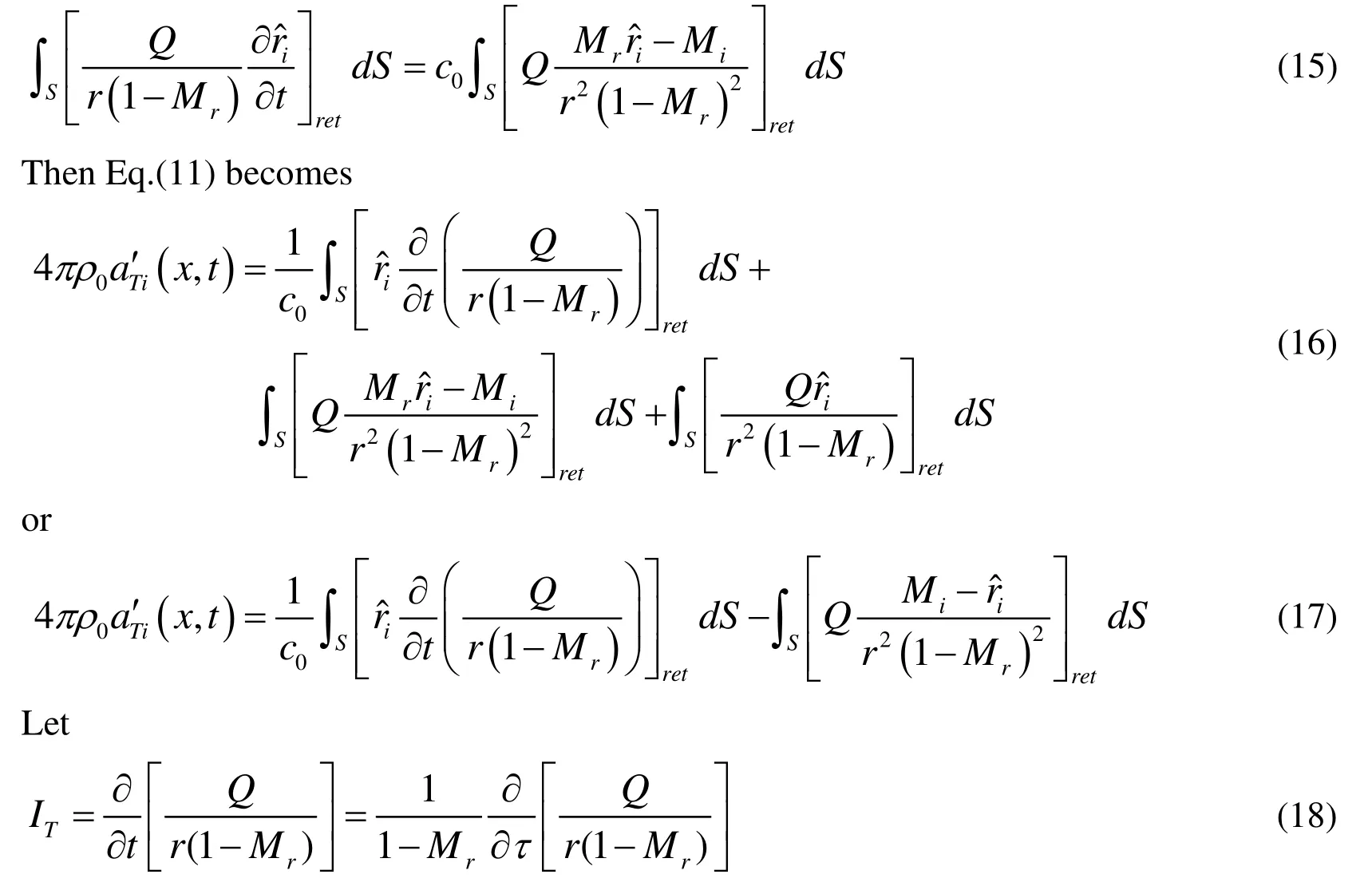
Expansion of the expression in the same manner as in the derivation of Farassat 1A gives

Next, simplifying Eq. (12) further, one can rewrite it as follows

Using Eq.(14), we have

Expansion of the expression in the same manner as in the derivation of Farassat 1A gives
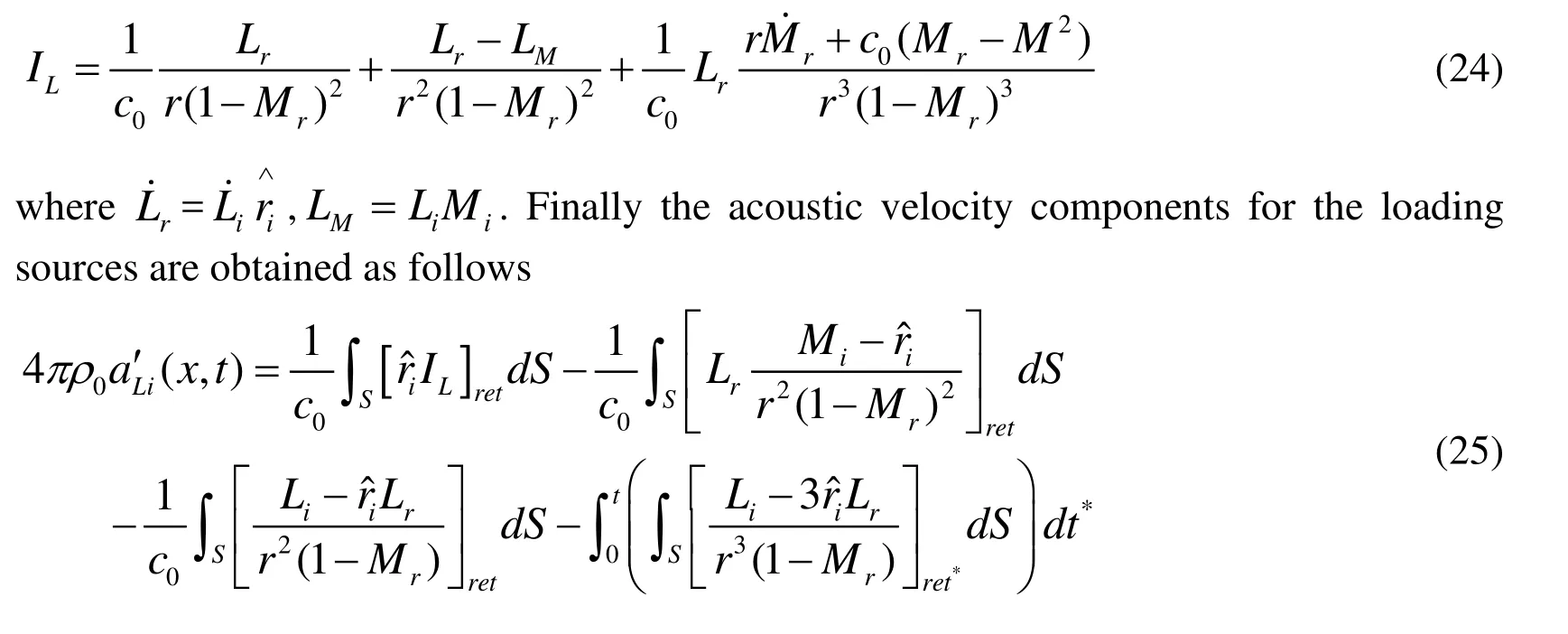
4 Thin-body acoustic boundary element method (BEM)
In this section, a thin-body boundary integral formulation is applied to calculate the far field sound pressure. Due to the scattering effect of the solid wall in the duct, the total sound pressure is acquired as the sum of the incident and scattered pressure


Figure 1: A diagram of acoustic scattering by a thin-body.

where n1and n2are normal unit vectors at the two sides of the wall,C+(x)and C?(x)are the two constants that depend on the position of x

Adding Eq. (27) and Eq.(28) gives the thin-body boundary integral equation
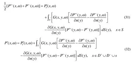
where ?/? n1=??/? n2=?/?n, and the continuous boundary conditions of the pressure and its partial derivation on the imaginary surface s are used

The assumption of acoustic rigid boundary conditions are used over the entire surface S

Then Eq.(31) and Eq.(32) reduce to

Eq.(36) is not sufficient to obtain the two unknowns P′+(x,ω)and P′?(x,ω).Differentiating Eq.(35) with regard to the direction of normal vector n(x), it can be transformed into

The problem of scattering by the duct can be dealt with initially solving Eq.(37) to calculate the sound pressure jump P ′+( y , ω ) ? P ′?(y,ω)on the surface S , and afterwards evaluating the acoustic pressure at any filed point. Then the acoustic pressure on both sides of the duct could be easily got. However, the value ofcannot be obtained easily by using Eq.(6) or Eq.(7). We can acquire it indirectly by using the acoustic velocity formulation. If Eq.(37) satisfies the Neumann boundary condition, we will

where vn={(x, ω ),(x, ω ),(x,ω)}for the thickness sources,vn={(x, ω ),x, ω ),(x,ω)}for the loading sources.
Then, to solve the Eq.(37), a discretized scheme based on BEM should be used to calculate the unknown value P ′+( y , ω ) ? P ′?(y,ω). The simplest constant boundary element is applied in this paper and the thin-body surface S is discretized into N elements. Each element has one node which is located in the center of the element. Then,Eq.(37) can be transformed into a system of algebraic equations.

Eq.(40) may be solved easily by using the software Mathematica. When the unknown ?is calculated, the acoustic pressure at any filed point can be obtained through Eq.(35)and (36).


5 Numerical results
In this part, the acoustic velocity field simulated by the derived formulation and scattering effect of the duct are validated through three test cases. The first case considers a monopole source, which is identified with a pulsating sphere. The second test case is a dipole source. The third case contains the consistency test known as the Isom thickness noise. All these sources are located at the center of the duct. Showing the validity and reliability of the developed formulation for acoustic scattering problems is our main work.The sound pressure is expressed as dB (decibels) and the predicted SPLs (sound pressure levels) is given by the following

5.1 Pulsating sphere
In order to verify the algorithms, the analytical solution of a monopole source has been investigated. The monopole is identified with a pulsating sphere as the small sphere with a radius a in Figure 2. The pressure fluctuation induced by the pulsating sphere is expressed by a harmonic spherical wave


Figure 2: Monopole source and data surface are shown.
where ωand k are angular velocity and the wave number, respectively, and

where A=4πa2U. To perform this case, we take the radius of the spherical penetrable data surface rsto be 3.25a . The speed of sound c0is 340m/s. The density for medium is 1.2kg/m3. The angular velocity of the source is 1020rad/s. The other parameters are a =0.01m and U =8m/s. The pulsating sphere is located at the center of the duct, which is shown in Figure 3. The diameter of the duct is 0.07m. The length of the duct is 0.5m.The observer distance is assumed to be 2m.
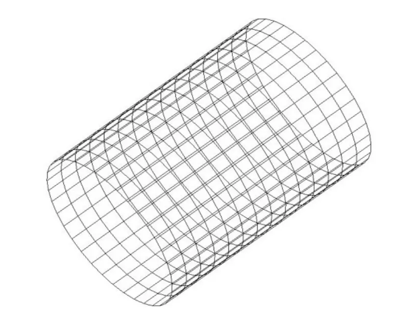
Figure 3: The duct in BEM.
The acoustic velocity components are calculated by using the numerical method. The results are compared with analytical solutions for different observer time. The x ,y and z components of the acoustic velocity obtained with the derived formulation is plotted in Figures 4-6. From Figures 4-6, we find that the numerical solutions are very good agreement with the analytical solution. To perform the acoustic scattering problems of the duct, we use the thin-body BEM. Figure 7 shows the scattering performance of the pulsating sphere. The left is the incident sound pressure, the middle is the scattering effect of the duct and the right is the total sound pressure.

Figure 4: The calculated x -component of acoustic velocity compared with that of the analytical solution for β1 = 1 8°. Monopole source.
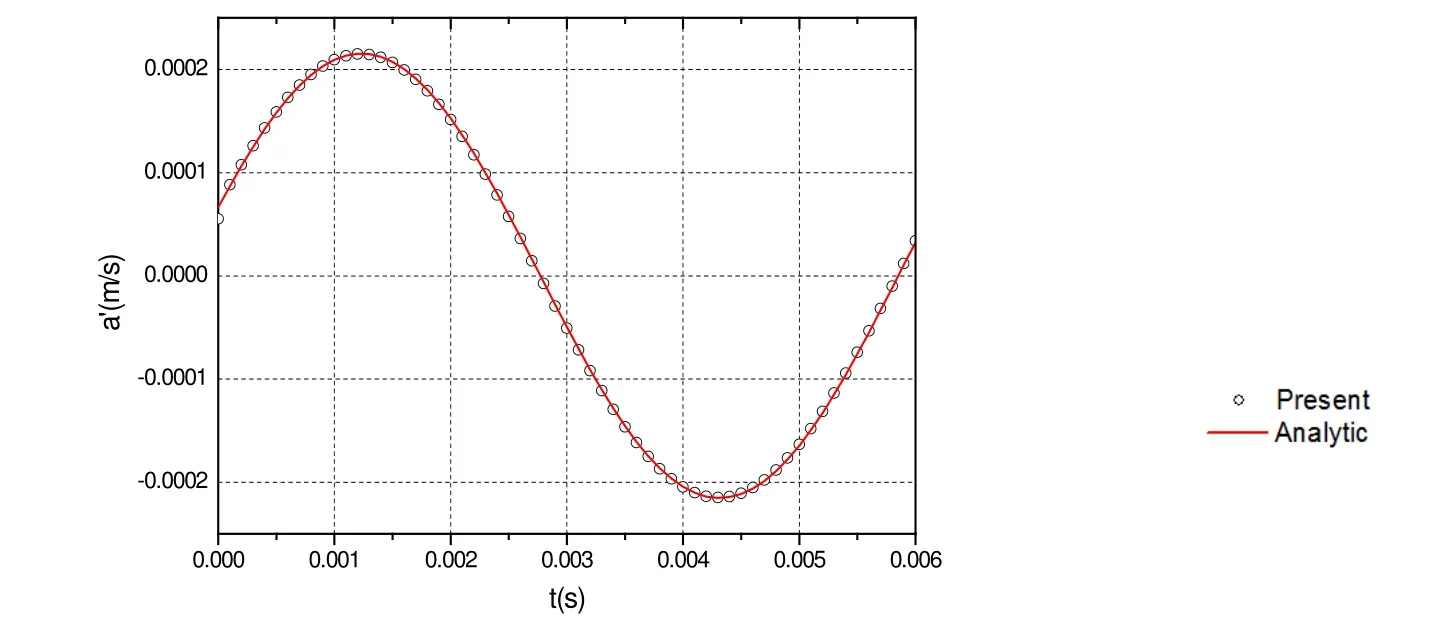
Figure 5: The calculated y -component of acoustic velocity compared with that of the analytical solution for β1 = 1 8°. Monopole source.
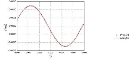
Figure 6: The calculated z -component of acoustic velocity compared with that of the analytical solution for β1 = 1 8°. Monopole source.
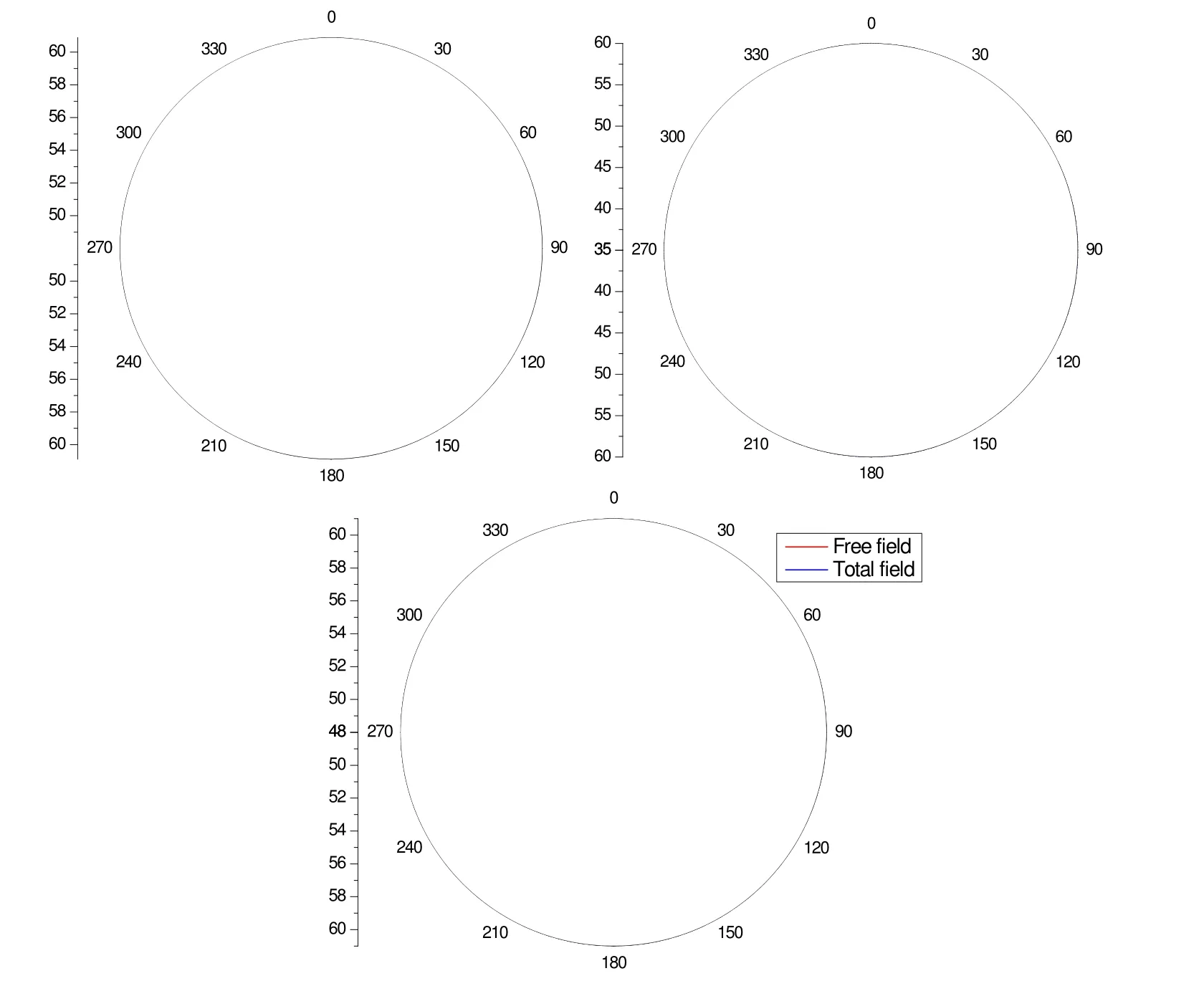
Figure 7: Directivity of calculated far-field SPLs at 4918 Hz (a) free field, (b) scattering effect of the duct and (c) total field. Monopole source.
From the Figure 7, we can see the directivity of the incident sound pressure is circular as the property of monopole sound source. When the scattering effect is considered, the directivity of the sum sound becomes non-circular. For the angle (210 to 330 degrees and 30 to 150 degrees), SPLs of the total field is louder due to scattering where at the angle (-30 to 30 degrees and 150 to 210 degrees), it is quieter. It shows that the sound pressure is strengthened in the direction of duct both ends, and the sound pressure is subdued in the other direction.
5.2 A three dimensional dipole source
A dipole point source is equivalent to a compact oscillating sphere, which is denoted as two closely positioned identical monopole point sources. A dipole has an axis, which is the line connecting the centers of the two monopoles (pulsating sphere with radius of a ).The monopoles are positioned in the z direction at a distance of d =2.5a from the center(d is the distance between the two monopole points). The pressure fluctuation induced by the dipole source for an observer positioned at (x,y,z )is

The integration surface used in the previous test case is also used here (rs=3.25a , in Figure 8). The other parameters are the same as the previous case. The observer distance is assumed to be 5m.

Figure 8: Dipole source and data surface are shown.
The calculation is performed for this case, and the acoustic velocity components are computed. The numerical results are compared with those of the analytical solution in Figures 9-11. Again, the numerical solution is in perfect coincidence with the analytical solution.
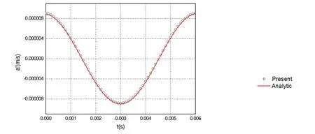
Figure 9: The calculated x -component of acoustic velocity compared with that of the analytical solution for β1 = 1 8°. Dipole source.
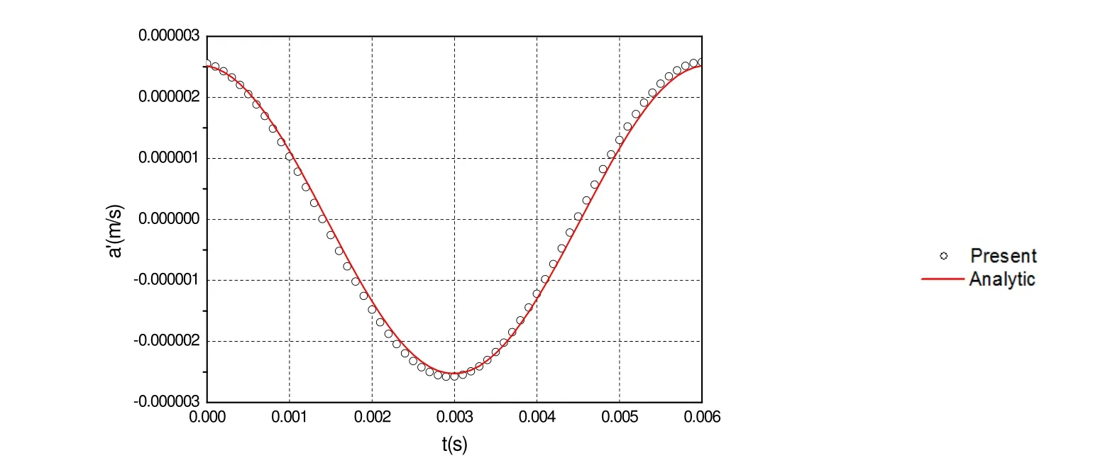
Figure 10: The calculated y -component of acoustic velocity compared with that of the analytical solution for β1 = 1 8°. Dipole source.
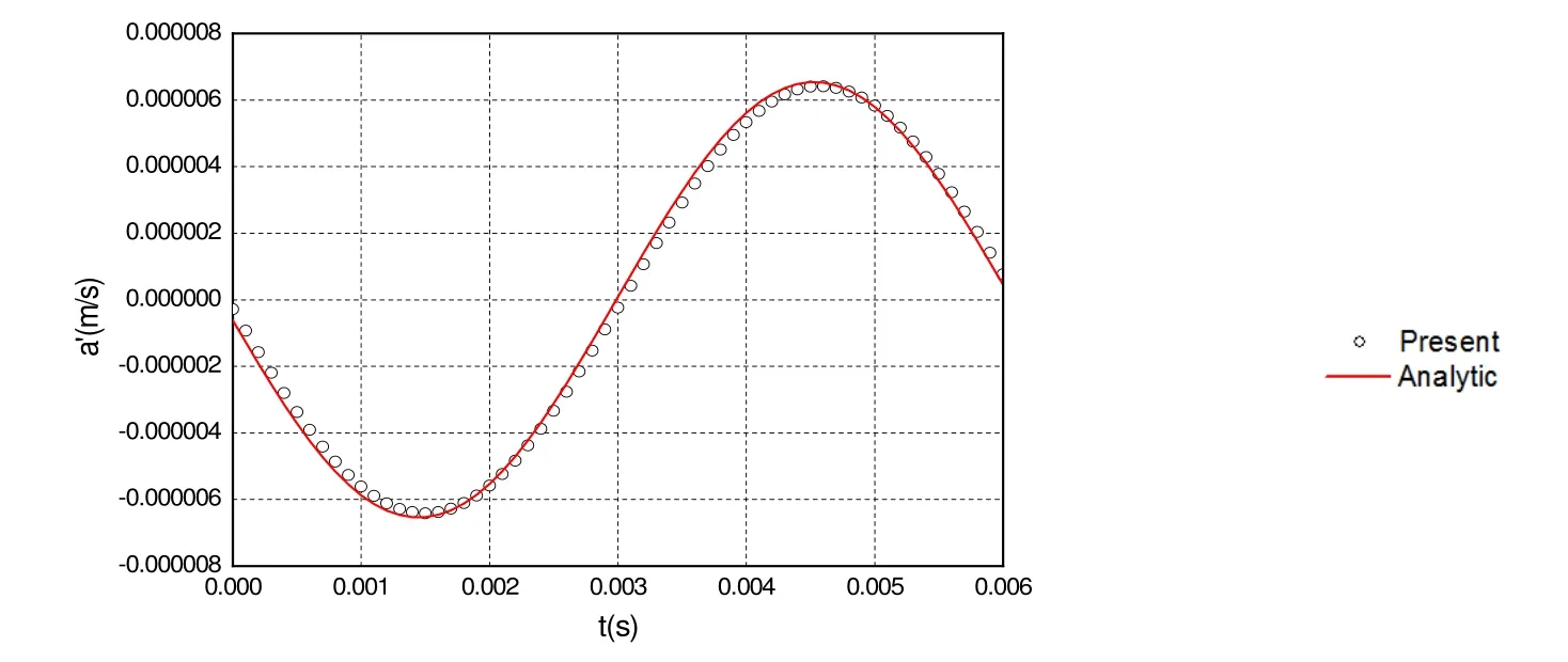
Figure 11: The calculated z -component of acoustic velocity compared with that of the analytical solution for β1 = 1 8°. Dipole source.
Figure 12 shows the scattering performance of the dipole source. The left is the incident sound pressure, the middle is the scattering effect of the duct and the right is the total sound pressure.
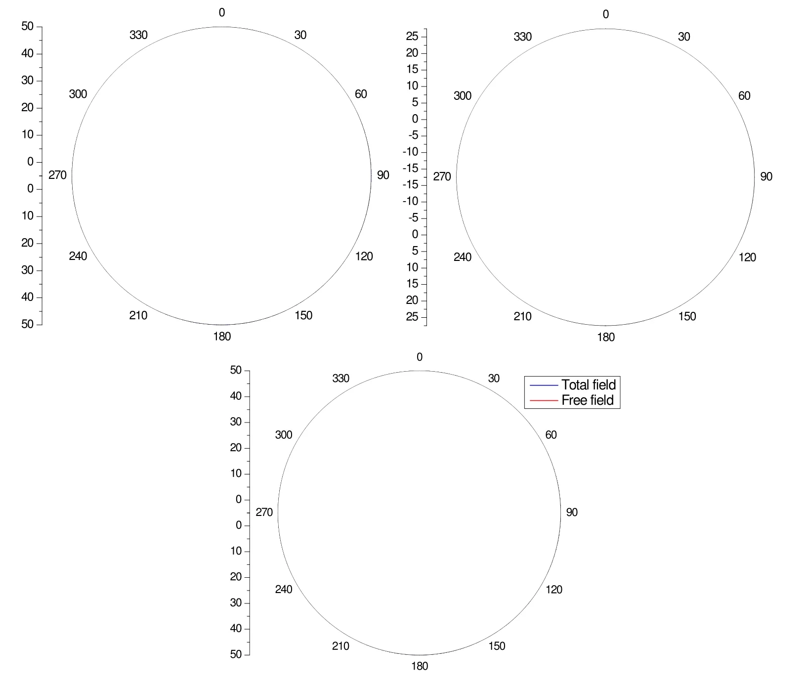
Figure 12: Directivity of calculated far-field SPLs at 4918 Hz (a) free field, (b) scattering effect of the duct and (c) total field. Dipole source.
From the Figure 12, we can find the directivity of the incident sound pressure is symmetrical as the property of dipole sound source. When the scattering effect is considered, the SPLs of the total field becomes slightly louder. It implies that the sound pressure of dipole source is strengthened through the duct scattering effect. The directivity of the total sound pressure is the same as the incident sound pressure.
5.3 Isom noise consistency
The Isom thickness noise property is discussed in [Brentner and Farassat (2003)]. When a constant aerodynamic load p=is used over a moving surface, the generated dipole loading noise should be identical to the monopole thickness noise. So we only consider the dipole loading noise for this problem.
In this case, we will show the scattering effect of the Isom noise consistency. The numerical example is applied to the noise generated by the flow around a helicopter tail rotor. The tail rotor consists of 11 equally spaced blades 0.594m in diameter with a constant chord of 0.056m. The CATIA geometric model of the tail rotor is shown in Figure 13. The blade tip Mach number is 0.8. The tail rotor is located at the center of the duct with diameter 0.7m, and length 1.5m. The observer is located 5m from the origin of the blade fixed frame.

Figure 13: Geometric model of tail rotor.
The incident sound pressure, the scattering sound pressure and the total sound pressure generated by the Isom source are shown in Figure 14.
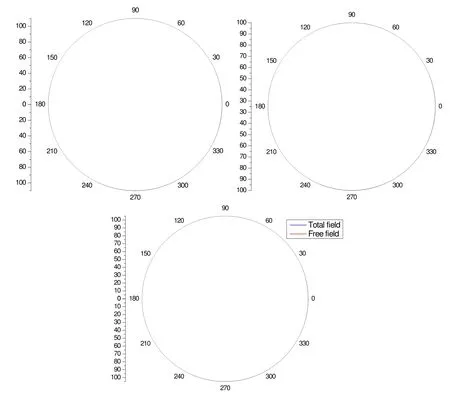
Figure 14: Directivity of calculated far-field SPLs at 4930 Hz (a) free field, (b) scattering effect of the duct and (c) total field. Isom noise source.
From the Figure 14, we can conclude the directivity of incident sound pressure and total sound pressure are the similar to the dipole noise source. The total sound pressure of Isom noise source is strengthened due to the duct scattering effect of the duct. However,the total sound pressure is slightly quieter in some local direction. The reason for the sound decreasing is likely due to noise cancellation.
6 Conclusion
The aim of this paper is to develop the FW-H/thin-body BEM method for studying the scattering effect of a duct numerically. An analytical formulation is derived for prediction the acoustic velocity generated by moving bodies. The acoustic velocity formulation can be used as boundary condition for thin-body BEM. Furthermore, a verification study was given based on three test cases: a pulsating sphere, a dipole source and Isom consistency test for helicopter tail rotor. The comparison is performed between analytical and numerical solution for acoustic velocity, and showed remarkable agreement. The scattering effect of duct for each case has been discussed. For the pulsating sphere, due to the scattering effect, the amplitude and directivity of SPLs are changed. For the dipole source, the amplitude only becomes greater.
Brentner, K. S.; Farassat, F. (2003): Modeling aerodynamically generated sound of helicopter rotors. Progress in Aerospace Science, vol.39, no.2, pp. 83-120.
Ciskowski, R. D.; Brebbia, C. A. (1991): Boundary element method in acoustics.Elsevier Science Publishing Co. Inc., New York.
Dunn, M. H.; Tinetti, A. F. (2008): Application of fast multipole methods to the NASA fast scattering code, 14thAIAA/CEAS Aeroacoustics Conference, AIAA, 2008-2875.
Dunn, M. H.; Tinetti, A. F.; Nark, D. M. (2015): Open rotor noise prediction using the time domain formulations of Farassat. Aeroacoustic, vol.14, no.1-2, pp. 51-86.
Ffowcs Williams, J. E.; Hawkings, D. L. (1969): Sound Generated by Turbulence and Surfaces in Arbitrary Motion. Philosophical Transactions of the Royal Society, vol.A264,no. 1151, pp.321-342.
Farassat, F.; Brentner, K. S. (1988): The Uses and Abuses of the Acoustic Analogy in Helicopter Rotor Noise Prediction. Journal of the AHS, vol. 33, no.1, pp.29-36.
Farassat, F.; Brentner, K. S. (1998): Supersonic Quadruple Noise Theory for High-Speed Helicopter Rotors. Journal of Sound and Vibration, vol.218, no.3, pp.481-500.
Ffowcs Williams, J. E.; Hawkings, D. L. (1969): Sound Generated by Turbulence and Surfaces in Arbitrary Motion. Philosophical Transactions of the Royal Society, vol.A264,no.1151, pp. 321-342.
Farassat, F. (2007): Derivation of formulations 1 and 1A of Farassat. NASA, TM 214853.
Ghorbaniasl, G.; Hirsch, C. et al. (2015): Acoustic velocity formulation for Kirchhoff data surfaces. Aerocoustics, vol.14, no.1-2, pp.105-132.
Huang, J.; Zhang, C. P.; Xiang, S. et al. (2015): Computation of aerodynamic noise radiated from open propeller using boundary element method. CMES-Computer Modeling in Engineering & Sciences, vol. 108, no.5, pp. 315-330.
Johnson,W. (1980): Helicopter Theory. Princeton University Press.
Kingan, M. J. (2014): Advanced open rotor noise prediction. Aeronautical Journal,vol.118, no. 1208, pp.1125-1135.
Kingan, M. J.; Powles, C.; Self, R.H. (2010): Effect of centerbody scattering on advanced open rotor noise. AIAA Journal, vol.48, no.5, pp. 975-980.
Lee, S.; Brentner, K.S.; Farassat, F. et al. (2009): Analytic formulation and numerical implementation of an acoustic pressure gradient prediction. Journal of Sound and Vibration, vol.319, no.3-5, pp. 1200- 1221.
Lee, S.; Brentner, K. S.; Morris, P. J. (2010): Acoustic scattering in the time domain using an equivalent source method. AIAA Journal, vol.48, no.12, pp. 2772-2780.
Mao, J. Y.; Zhang, Q. L.; Xu, C.; Qi, D. T. (2015): Two Types of Frequency-Domain Acoustic Velocity Formulation for Rotating Thickness and Loading Sources. AIAA Journal, vol.53, no.3, pp.713-722.
Mao, J. Y.; Qi, D. T. (2009): Computation of rotating blade noise scattered by a centrifugal volute. Proceedings of Institution of Mechanical Engineers, Part A: Journal of Power and Energy, vol.223, no.8, pp. 965-972.
McAlpine, A.; Astley, R.; Hii, V. et al. (2006): Acoustic scattering by an Axiallysegmented Turofan inlet duct liner at supersonic fan speeds. Journal of Sound and Vibration, vol. 294, no. 4-5, pp. 780-806.
Qian, Z. Y.; Han, Z. D. ; Atluri, S. N. (2013): A fast regularized boundary integral method for practical acoustic problems. CMES-Computer Modeling in Engineering &Sciences, vol. 91, no.6, pp. 463-483.
Swift, S.; Blaisdell, G.; Lyrintzis, A. (1983): A time domain equivalent source method for acoustic scattering with coincident source and control points. AIAA, 2013-2017.
Tausch, J.; Xiao, J. (2010): A spectral boundary element method for scattering problems.CMES-Computer Modeling in Engineering & Sciences, vol. 58, no.3, pp. 221-245.
Wu, T. W. (2000): Boundary element acoustics: fundamentals and computer codes, WIT Press, Southampton.
Wu, T. W.; Wan, G. C. (1992): Numerical modeling of acoustic radiation and scattering from thin bodies using a Cauchy principal integral equation. J. Acoust. Soc. Am., vol.92,pp. 2900- 2906.
 Computer Modeling In Engineering&Sciences2017年1期
- Computer Modeling In Engineering&Sciences的其它文章
- Modeling of Canonical Switching Cell Converter Using Genetic Algorithm
- Reliability Analysis for Complex Systems based on Dynamic Evidential Network Considering Epistemic Uncertainty
- A Study on the Far Wake of Elliptic Cylinders
- Optimization of Nonlinear Vibration Characteristics for Seismic Isolation Rubber
- Stability Analysis of Cross-channel Excavation for Existing Anchor Removal Project in Subway Construction
- Inverse Analysis of Origin-Destination matrix for Microscopic Traffic Simulator
