Synthesis of Hierarchically Porous FAU/γ-Al2O3Composites with Different Morphologies via Directing Agent Induced Method
Wang Jia; Zhao Tianbo; Li Zunfeng; Zong Baoning; Du Zexue; Zeng Jianli
(1. Key Laboratory of Cluster Science of Ministry of Education, Beijing Institute of Technology, Beijing 100081; 2. SINOPEC Research Institute of Petroleum Processing, Beijing 100083)
Synthesis of Hierarchically Porous FAU/γ-Al2O3Composites with Different Morphologies via Directing Agent Induced Method
Wang Jia1; Zhao Tianbo1; Li Zunfeng1; Zong Baoning2; Du Zexue2; Zeng Jianli2
(1. Key Laboratory of Cluster Science of Ministry of Education, Beijing Institute of Technology, Beijing 100081; 2. SINOPEC Research Institute of Petroleum Processing, Beijing 100083)
Zeolite FAU composites with a macro/meso-microporous hierarchical structure were hydrothermally synthesized using macro-mesoporous γ-Al2O3monolith as the substrate by means of the liquid crystallization directing agent (LCDA) induced method. No template was needed throughout the synthesis processes. The structure and porosity of zeolite composites were analyzed by means of X-ray powder diffraction (XRD), scanning electron microscopy (SEM) and N2adsorption-desorption isotherms. The results showed that the supported zeolite composites with varied zeolitic crystalline phases and different morphologies can be obtained by adjusting the crystallization parameters, such as the crystallization temperature, the composition and the alkalinity of the precursor solution. The presence of LCDA was defined as a determinant for synthesizing the zeolite composites. The mechanisms for formation of the hierarchically porous FAU zeolite composites in the LCDA induced synthesis process were discussed. The resulting monolithic zeolite with a trimodal-porous hierarchical structure shows potential applicability where facile diffusion is required.
monolithic FAU/γ-Al2O3composites; hierarchically porous; different morphologies; directing agent induced method
1 Introduction
Acidic Y-zeolite with highly stable faujasite crystalline framework of 0.74 nm openings is the most active and selective component of the fuid catalytic cracking (FCC) catalysts, however, the sole pore of the Y zeolites limit their applications involving bulky molecules, which can generate diffusion limitation and coke deposition to have a negative infuence on catalytic activity, selectivity and catalyst lifetime[1-2].
Hierarchical porous materials integrate multiple levels of porosity, which is expected to decrease the diffusion resistance and increase the accessibility to the zeolite pores in catalytic applications[3]. This is particularly important for the diffusion of large molecules in viscous systems. In zeolites, the hierarchy can be attained by introducing an additional mesopore system within an individual zeolite crystal or by fabricating a zeolite supported structure[4-5]. The incorporation of mesopores into the microporous zeolite usually uses the soft-templating methods, which can assist surfactants in the formation of mesopores[6-7]. However, the cost of the templates would be of concern about the scalability and large scale application of mesoporous zeolites that are prepared by using these approaches.
The zeolite supported structures considered thereby, including zeolite flms and coatings[8]grown on various architectures (i.e., honeycombs[9-10], paralleled macropores[7,11-12], open porous foams[13], porous disks[14-16], tubes[17-19], monoliths[20-24]), and natural materials (i.e., mullite[16,18], silica[10], cordierite[22],[14-17,19,21,23], diatomite[7,11-12,24], aluminosilicate[20], kaolin[25], calcium silicate[26], metals[27-28], silicon carbide[9],), can be achieved by means of different techniques, viz.: the insitu hydrothermal synthesis, the seeding techniques, the dip-coating techniques, and the partial conversion of the support. Wang, et al.[11]reported a macro-microporous sil-icate-1 composites synthesized by transforming in vapor phase the diatomaceous silica into zeolite with the aid of various nanozeolite seeds via the layer-by-layer assembly technique, while the seed preparation needed TPAOH or TEAOH serving as structure-directing agents (SDA) and an additional calcination step for the process. The zeolite nucleation can be accelerated by modifying the support surface or using zeolitic liquid crystallization directing agent (LCDA) as a component of precursor solution. Huang, et al.[15]employed 3-aminopropyltriethoxysilane (APTES) as the covalent linker between the FAU layer and the α-Al2O3support to change the zeta potential of the substrate and promote the nucleation, and then a well intergrown FAU membrane was thus formed without seeding. LCDA containing seeding nuclei were usually referred to the synthesis of NaY zeolite, since the seed gel involved in the precursor solution can form a continuous FAU membrane[19-28]or interact with SDA to produce the hierarchically porous FAU composites[2,25,30].
The application of the synthesized zeolite flms on porous substrates were mainly implemented in the field of gas or liquid separation[31], but they were solely used as catalysts. On the other hand, prior to the synthesis, the chemical pretreatment of the substrates[16,32]and the multi-step synthesis[9,13]were necessary to increase the chemical affnity between the zeolite and its carrier in order to achieve easier nucleation on the substrates and obtain the defect-free membrane, which would complicate the synthesis procedure. As a catalyst, zeolite membrane can combine the catalysis procedure with adsorption and separation processes to increase the percentage of transition[33].
However, there is still a big challenge to introducing both mesopores and macropores into zeolitic materials nowadays[5,25]. The introduction of macropores accompanied by using “hard template”[10]and the resulting powdery sample[29]would increase the cost of the preparation process and limit the industrial application of the porous zeolite. Since the monolithic structures have the advantages of higher surface area-to-volume ratio, lower pressure drop and easy scaling up[34], monolithic zeolite composites can be easier to shape in an appropriate morphology along with good performance in the catalytic applications. Tokudome, et al. first used monolithic macro-mesoporous α-Al2O3as support and alumina source to fabricate trimodal porous high-silica and low-silica zeolite monoliths with TPAOH or NaOH as SDA[21]. The same support synthesized via the sol-gel process accompanied by phase separation was employed by Sun, et al. to prepare macro-meso-microporous MFI zeolite composites using the seeding and secondary growth method withn-butylamine functioning as SDA[35]. In our previous work, we prepared hierarchically porous MFI and beta type composites by transforming the Nakanishi type silica or silica-alumina monolith via the dry-gel transforming method[36-41]or using carbon as a transitional template[40,42]to maintain the monolithic shape.
γ-Al2O3as one of the transition aluminas can be used as adsorbents, catalysts, and catalyst supports thanks to its excellent textural and chemical properties. The large specific surface area and good stability of γ-Al2O3make it suited to disperse zeolite crystals[43]. In present work, we prepared hierarchically porous FAU/γ-Al2O3composites with different morphologies by the LCDA induced method, and the zeolites can be deposited on the monolithic macro-mesoporous γ-Al2O3as separated particles, layers, and as the support skeleton zeolite form with trimodal pores. The monolithic shape of the γ-Al2O3support can be maintained owing to its high alkali resistance during the in-situ crystallization process. The formation of impurity phases was suppressed through the optimization of precursor solution containing LCDA. The structural and morphological evolutions of monolithic zeolite/ γ-Al2O3composites during synthesis under different conditions were tracked down by XRD and SEM analyses. To the best of our knowledge, there were rarely reports on the synthesis of FAU zeolite monoliths with different morphologies without using any “sacrificial templates”.
2 Experimental
2.1 Synthesis of macroporous alumina monoliths (M)
The hierarchically porous γ-Al2O3used as the support was prepared according to the method previously reported by Yasuaki Tokudome, et al[44]. The difference was that we conducted a large-scale synthesis of monolithic alumina with a given crystal style.
The synthesis was performed with aluminum chloride hexahydrate (AlCl3·6H2O, Xilong Chemical Co., Ltd) used as the aluminum source. Polyethylene oxide (PEO, viscosity averaged molecular weightMv=1×10⁶, Changchun Huagao Fine Chemical Co., Ltd.) was used as a polymer to induce the phase separation. Propylene oxide (PO, Sinopharm Chemical Reagent Co., Ltd.) was added to initiate gelation. A mixture of deionized (DI) water and ethanol (EtOH, Beijing Chemical Plant, 99.5%) was used as the solvent. All reagents were used as received.
The detailed preparation of the alumina gel was carried out as follows. Firstly, 2.7 g of PEO were dispersed into 137.4 g of EtOH in a plastic cup under magnetic stirring, after that 113.1 g of DI water were added slowly under stirring in an ice-cooled environment to accelerate the dissolution of the polymer with high molecular weight. After the PEO was completely dissolved, the magnetic stirring was replaced by mechanical agitation before adding 129.6 g of AlCl3·6H2O. 93.3 g of PO were not added until the aluminum source was dissolved thoroughly. After being subject to stirring for 5 min, the obtained homogeneous solution was transferred into sealed plastic tubes (5 mL in volume, with an i. d. of 1 cm) for gelation at 313 K. Secondly, the resultant wet gel was then subject to ageing at 313 K for 24 h, then the aged wet gel was placed into evaporating dishes covered with a preservation flm which was provided with several small holes made by shear. The evaporating dishes were transferred into a preheated oven at 313 K for 2 days to evaporate the solvent and produce dried gel. Finally, the obtained dried gel was calcined at 1073 K for 2 h in air at a heating rate of 283 K/min to get γ-type alumina with hierarchical pores. It should be prudent to make the reaction container covered with a preservation film to reduce the evaporation of the solvent. Furthermore, the container was then placed in a constant-temperature ice-water bath maintained at 273 K to absorb the heat released from the hydrolysis-polycondensation reaction.
2.2 Synthesis of monolithic zeolite composites
All chemicals were directly used as received without any further purification. The reactants used in this section were as follows: sodium hydroxide pellets (NaOH, 96%, Xi Long Chemical Co., Ltd), water glass (SiO2, 26.0%, Na2O, 8.2%, Beijing Hongxing Natron Factory), sodium aluminate (NaAlO2, Al2O3≥41%, Sinopharm Chemical Reagent Co., Ltd.) and DI water.
In order to understand the role of the LCDA in the structured zeolite composites, three synthetic solutions were prepared according to the following procedure:
A seed gel having a molar composition of 10.8 Na2O:1.0 Al2O3: 10 SiO2:200 H2O was preliminary prepared and dynamically aged for 24 h at room temperature.
A feedstock gel with a molar composition of 4.63 Na2O:1.0 Al2O3: 10 SiO2: 200 H2O was prepared afterwards. Finally, a part of the seed gel was added to the feedstock gel to form an overall gel having a molar composition of 5.4 Na2O: 1.0 Al2O3: 10 SiO2: 200 H2O, which can be designated as “S+F”.
The γ-Al2O3monoliths (M) were selectively added into the above gel under vacuum for 30min to force the saturated gel into the interconnected macropores of the substrate, and were then dried in air at 383 K for 1 h. The monoliths should be immersed in the aged seed gel that had been already aged for 24 h, followed by being immersed into the overall gel which was then subject to ageing altogether for 24 h at room temperature. The preparation procedure is schematically depicted in Figure 1. The γ-Al2O3monoliths that had been treated with the seed gel of the first step were denoted as MS0. After the secondary step of treatment with the feedstock gel, the samples treated with overall gel of the third step before and after hydrothermal reaction were designated as MSFSF and MS-F-SF respectively. The in-situ hydrothermal crystallization of MS-F-SF was carried out at 373 K for 5 h.
To investigate the infuence of crystallization parameters involving the alkalinity of the precursor solution and the crystallization temperature on the zeolite composites, the pretreated monolith with the aged seed gel was subsequently immersed in the precursor solution with a proper composition to be subject to ageing for 24 h at room temperature. At the end of the ageing time, the support with the mixture was transferred into a Teflon container and the container was heated to different temperature for 5 h. Once the synthesis was completed, the support was removed from the synthesis mixture,rinsed with DI water until the pH value reached below 9 and was dried at 383 K for 1 h. The sample identifcation codes under varying synthesis conditions are listed in Table 1.
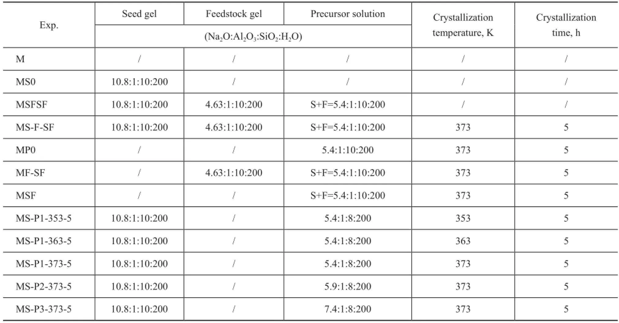
Table 1 Conditions of the treatment for synthesizing monolithic zeolite/γ-Al2O3composites
2.3 Characterization
The XRD patterns were recorded on a Shimadzu 7 000 diffractometer using Cu Kα radiation (40 kV, 30 mA) at a scan rate of 10°/min with a step size of 0.02°, and at a scanning angle (2θ) ranging from 5° to 80°.
The microstructures of the fractured surfaces of the samples were observed by SEM micrographs taken with a HITACHI S-4800 scanning electron microscope (25 kV). Nitrogen adsorption-desorption experiments were carried out at 77 K on a Micrometrics QUADRASORB SI sorption analyzer. All samples were degassed at 573 K prior to each measurement. The micropore volume and micropore surface area were determined by the t-plot method. The mesopore size distribution, the mesopore volume and the mesopore surface area were calculated from the adsorption branch using the Barrett-Joyner-Halenda (BJH) method, and the surface area was determined using the Brunauer-Emmett-Teller (BET) method. The total pore volume was evaluated atp/p0=0.99. The pore size distribution (PSD) was determined using the non-local density functional theory (NLDFT) method provided by Quantachrome’s data reduction software for the N2isotherms collected.
3 Results and Discussion
3.1 The structural and morphological evolution of γ-Al2O3composites during the multistage treatments
Our three-stage pretreatment process is composed of: (1) seed gel pretreatment (immersion in the aged seed gel, at 383 K dried for 1h); (2) feedstock gel pretreatment (immersion in the feedstock gel, at 383 K dried for 1h); and (3) overall gel pretreatment (immersion in the overall gel to be further aged for another 24 h, at 383 K dried for 1h) before hydrothermal crystallization.
The photograph of Figure 1 clearly shows the parent M retaining the appearance of the synthesis vessel except for a shrinkage of approximately 80%, the various shapes needed for the practical applications can be molded by using gelation vessels with different shapes.
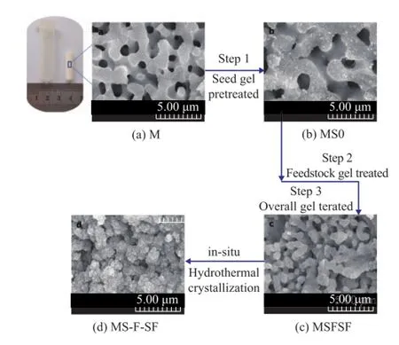
Figure 1 Schematic of the typical multi-stage treatment synthesis procedure of hierarchically monolithic FAU/ γ-Al2O3composites
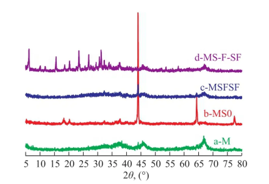
Figure 2 XRD patterns of monolithic γ-Al2O3(a) and γ-Al2O3composites obtained after multi-stage treatments (b-d)
Figure 2 shows the XRD patterns of γ-Al2O3composites collected from each stage of treatment and the hydrothermal reaction mixture after the three-step treatment. The XRD profile of M (Figure 2a) shows the typical XRD pattern of γ-Al2O3. The broad width of diffraction peaks indicates the precipitation of nanocrystalline γ-Al2O3from the amorphous phase[44]. The image of M (Figure 1a) displays three-dimensionally interconnected macropores with a diameter of ca. 0.5—2 μm. As shown in Figure 2b, the XRD peaks at 45.8° and 67° of the 2θvalues assigned to γ-Al2O3disappeared, and in this case, however, new peaks appeared at 18°, 20°, 44°, 64.5° and 77°, which were attributed to the formation of gibbsite phase (PDF#01-0263) of MS0. With regard to MSFSF, the gibbsite phase almost disappeared except for the diffraction peaks at 44°, and meanwhile, the broad peaks of γ-Al2O3appeared again. After hydrothermal crystallization at 373 K for 5 h, the sample collected from MS-FSF exhibited strong zeolite peaks at 6.2°, 15.5°, and 23.5° with (h l k) values being equal to (111), (331) and (553), assigned to faujasite-Na (PDF#12-0228) on the basis of the broad peaks of γ-Al2O3, indicating to the formation of NaY/γ-Al2O3composites. No other zeolite peaks can be observed from XRD pattern, which confrms that the resulting zeolite contains NaY zeolite only. Moreover, the smooth skeletons of the monolithic alumina of MS-F-SF (Figure 1d) were transformed into aggregates of zeolite Y crystals with octahedral morphology of ca. 0.5 μm. The SEM images of Figure 1 also show the change of the micro-morphology during the transition of M substrate into zeolite Y/γ-Al2O3composites. After the treatment of the seed gel, the feedstock gel and the overall gel, the morphology of MS0 (Figure 1b) and MSFSF (Figure 1c) had well preserved the interconnected skeletons and macropores of M. However, compared to the smooth inner surface and homogeneous fractured skeleton surface of M, the sample of MS0 exhibited the randomly rough surface with prismatic particles, about 0.5 μm in length, which were distributed on the inner surface or skeletons of M, while MSFSF in the shape of spherical particles had a diameter of ca. 0.5 μm. The surface and skeleton roughness with new particles were formed likely due to partial dissolution and interaction between the substrates and the gel after multistage treatment under the basic condition. Several studies have shown that the physical structure and chemical nature of the support have a strong infuence on the deposition of zeolites[16,32]. Compared to α-Al2O3substrate, γ-Al2O3with more oxygenated surface functional groups may provide suitable nucleation sites for zeolite. Through the covalent linkages with surface hydroxyl groups of M[15,28], the treated gel were likely adsorbed into the support skeleton, which were organized by the aggregation of primary or secondary particles of γ-Al2O3. After the three-stage treatment, the nucleated substrate skeleton became a high-purity zeolite Y/γ-Al2O3composite after crystallization, as determined by XRD and SEM analyses. The retaining of the original morphology can be explained by a pseudomorphic transformation in which the solid-state aluminum source transforms into a crystalline zeolite without migrating away into the solution phase[45].
3.2 Effect of the addition of the seed gel on the zeolite loading
Without undergoing the first step of seed gel treatment, the MP0, MF-SF and MSF samples were synthesized to investigate the role of seed gel, feedstock gel or overall gel treatment in the formation of FAU zeolite composites. The sample of MP0 was prepared by immersing M into the precursor solution with the same ratio of overall gel prior to being subject to ageing for 24 h before it was crystallized at 373 K for 5 h. The morphology of MP0 (Figure 3a) retained the interconnected macropores of M, except for some isolated particles of around 1 μm in diameter. Additionally, the homogeneous skeleton surface of the original M showed some particles with a diameter of less than 0.5 μm, and the variation might be caused by the formation of bayerite phase, which was characterized by the XRD pattern in Figure 3b. With the addition of seed gel existing in the overall gel as the precursor solution, MF-SF and MSF were prepared with or without the feedstock gel treatment, respectively. The XRD patterns are shown in Figure 3d and 3f, and besides the peaks originated from the support, peaks assigned to zeolite Y were observed, indicating that the zeolite Y was the only species on the support and the zeolite Y/γ-Al2O3composites were thus produced. Both the SEM images of MF-SF and MSF exhibited that the zeolite layer was deposited on the surface of the interconnected macroporous M substrate. The morphology and zeolite layer thickness determined by FE-SEM are shown in Figure 3c and 3e. The image of MF-SF (Figure 3c) shows a dense intergrown layer of less than 0.5 μm in thickness consisting of NaY crystals with the typical bi-pyramidal form frmly attached to the substrate surface. It can be seen from the porous surface of the cross section that the crystals were only partly complete as their growth was stopped in the direction of the support, and the crystals seemed as if they were growing from the support. The continuous zeolite layer can be seen in the inner surface of the macropores. However, with regard to MSF, the walls of the recrystallized monolith were uniformly covered with a continuous 0.5 μ-thick layer of intergrown fne NaY crystals (Figure 3e). In addition, the inner surface of the through porous skeleton could not be seen because some of the macropores were blocked by the zeolite layer which grew along the porous surface. There are obvious differences in the morphology between MS-SF and MSF formed by different synthesis procedures. Compared to MSF without the feedstock gel pretreatment, a layer of gel could be formed on the surface of MF-SF after the pretreatment, and the gel solution with a large amount of reagents might be produced during ageing and crystallization of the overall gel, thus the formation of nuclei in the bulk phase would dominate instead of the growth of seed crystals and then a less thick layer was formed on the porous surface. On the contrary, the comparatively dilute clear solution resulted from MSF could promote the growth of seed crystals and made zeolite layers more compact and dense[17]. It could be concluded that the employment of seed gel as the starting material was a prerequisite for the successful formation of FAU zeolite composites. Specifcally, the mode of seed gel treatment had a signifcant effect on the morphology of the resulting zeolite composites. The seed gel appeared as a component of the precursor solution was a determining factor for the coverage of the support, which was in accordance with the results of Clet, et al[28]. With the pretreatment of seed gel in the frst step, MS-F-SF obtained via the pseudomorphic transformation might be caused by the seed gel that was well spread over the surface and the skeleton of the γ-Al2O3composites.
The samples of MS-F-SF, MF-SF or MSF obtained by multi-step pretreatments or overall gel which contained seed gel pretreatment can provide initial-bred nuclei to catalyze the nucleation of the desired zeolite phase, making it possible to limit the exposure of aluminate support to the caustic environment and thus preventing the deposition of foreign zeolite phases[27].
3.3 Effect of the Na2O/Al2O3ratio of precursor solution on the zeolite loading
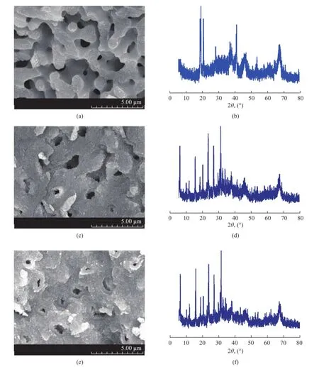
Figure 3 SEM images and XRD patterns of γ-Al2O3composites crystallized at different conditions without seed gel pretreatment
As the seed gel played a crucial role in the formation of hierarchically porous NaY zeolite composites, the synthesis procedure was furthermore simplified by the pretreatment of LCDA followed by ageing the substrates in the precursor solution containing different Na2O/Al2O3ratios for 24 h prior to the hydrothermal treatment at 373 K for 5h, the samples obtained thereby were labeled as MS-P1-373-5, MS-P2-373-5 and MS-P3-373-5, respectively. Figure 4 shows the XRD patterns of the resulting samples. The XRD profle of the synthesized composites matched well with the patterns of standard zeolite Y and γ-Al2O3, except for the peaks of zeolite A or hydroxysodalite refections. LTA phase is a common by-product in the synthesis of FAU-type zeolite and sometimes they would compete for a share in the product slate. The hydroxysodalite phase was not detected until the Na2O/Al2O3ratio increased to 7.4, corresponding to the sample of MSP3-373-5 (Figure 4c). The appearance of zeolite A and hydroxysodalite along with zeolite Y might be caused by the existence of β-cage, which is the common structural basis for the constitution of the three zeolite phases[46]. The intensity of zeolite Y reflection decreased with an increasing Na2O/Al2O3ratio. The increased alkalinity of the precursor solution might induce the decreased polymerization degree of silicate and aluminate, which was not conductive to the formation of nuclei and could lead to a decreased crystallinity[30]. The SEM micrographs of samples are displayed in Figure 5. The skeletons of MS-P1-373-5 (Figure 5a) were composed of aggregates of zeoliteY crystals with octahedral morphology of ca. 0.5—0.8 μm in diameter, which agreed well with the result verifying the highest crystallinity of the XRD analysis. The formation of MS-P1-373-5 was similar to the pseudomorphic transformation process of MS-F-SF, indicating that the seed gel pretreatment might spread to the skeleton and the inner surface of the substrate, and with the addition of the dissolution of skeleton aluminum, the further polycondensation and rearrangement of the resulted aluminosilicate gel could form the hierarchically porous zeolite composites, which was traditionally described as“solid-state” crystallization[7]. With higher Na2O/Al2O3ratio of 5.9, the image of MS-P2-373-5 (Figure 5b) displayed that the typical octahedrally shaped NaY crystals with the size in the range of 0.5—1 μm were loosely deposited on the surface of the substrate. Because of the leakage of aluminium from the support into the synthesis gel in the stronger alkalinity circumstances, the Y zeolite crystals would grow preferentially in the liquid phase of the through pores rather than on the surface of substrate. Further increased basicity induced the extensive dissolution of γ-Al2O3support and the decrease in regularity of macroporous morphology as observed in Figure 5c, and the cubically shaped NaA particles, less than 1 μm in diameter, were deposited on the surface of the support skeleton, which was coincident with the XRD pattern and confrmed the leakage of aluminum from the substrate additionally.
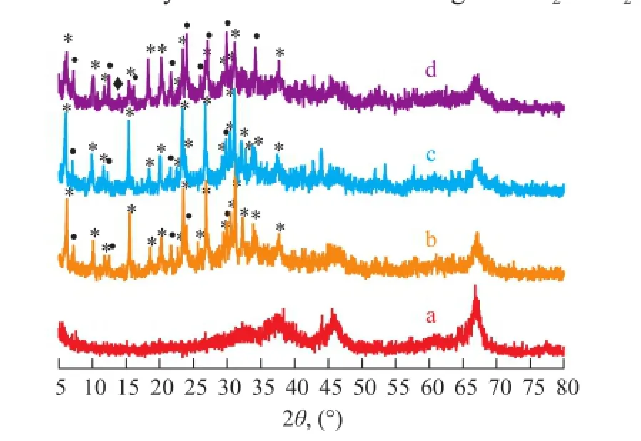
Figure 4 XRD patterns of FAU/γ-Al2O3composites synthesized at different Na2O/Al2O3ratio of the precursor solution
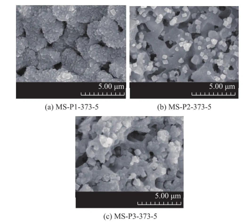
Figure 5 SEM images of FAU/γ-Al2O3composites synthesized at different Na2O/Al2O3ratio of the precursor solution
Any attempt to grow zeolite Y on M by the only pretreatment of seed gel had caused the support corrosion and precipitation of several silico-aluminate impurities.
3.4 Effect of crystallization temperature on zeolite loading
To study the effect of crystallization temperature on the zeolite loading, the LCDA pretreated substrates were immersed into the precursor solution at a certain composition and were aged for 24 h prior to crystallization at different temperatures for 5 h. The sample formed thereby was labeled as MS-P1-x-5, where x represented the crystallization temperature (in K). The formation of hierarchically porous zeolite structures was monitored by XRD, SEM and N2sorption techniques. Figure 6 shows the XRD patterns of the resulting samples. Apart from the peaks of zeolite A and hydroxysodalite reflections, the XRD profle of the synthesized composites matched well with the patterns of standard zeolite Y and γ-Al2O3. With the increase in synthesis temperature, the intensity of FAU peaks was enhanced, while the peak of zeolite hydroxysodalite decreased. The result strongly suggests that high crystallization temperature at 373 K can suppress the impure phase of hydroxysodalite, which is coincident with Figure 4. The image of MS-P1-353-5 sample (Figure 7a) exhibited intergrown layers less than 0.5 μm in thickness, which consisted of NaY crystals with the typical bipyramidal form, ca. 0.3 μm in diameter, which was frmlydeposited on the walls of the support skeleton. Seeding is a known technique in zeolite synthesis that can promote a significant synthesis time reduction and the precipitation of small crystals with a narrow size distribution. The LCDA pretreatment is a mode of seeding. The small crystal size of MS-P1-353-5 confrms the presence of larger concentration of nucleating particles. After having been subject to crystallization at 363 K for 5 h, the octahedral morphological FAU zeolites with a crystal size of ca. 1 μm were homogeneously deposited on the inner surface of the support in the sample MS-P1-363-5 (Figure 7b). The image of MS-P1-373-5 with a pseudomorphically transformed morphology is displayed in Figure 5a.
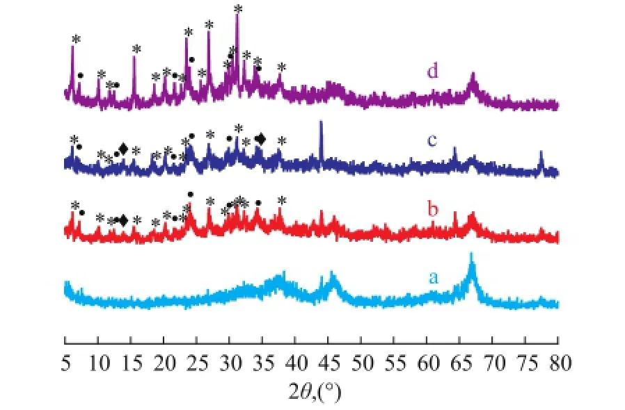
Figure 6 XRD patterns of FAU/γ-Al2O3composites synthesized at different crystallization temperatures
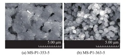
Figure 7 SEM images of FAU/γ-Al2O3composites synthesized at different crystallization temperatures
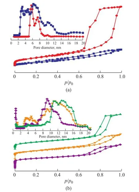
Figure 8 N2physisorption isotherms and DFT pore size distribution of samples before (a) and after (b) crystallization at different temperatures

Table 2 Textural parameters of the macroporous γ-Al2O3, the seed gel pretreated γ-Al2O3and FAU/γ-Al2O3composites with different morphology formed at different crystallization temperature
The nitrogen adsorption-desorption isotherms of γ-Al2O3and γ-Al2O3composites before and after crystallization at various temperatures are shown in Figure 8, with the corresponding NLDFT PSD depicted in the inset. The isotherms of as-synthesized samples can be classifed as type IV according to the IUPAC classification, signifying the existence of mesopores. The slight increase in adsorption occurred whenp/p0> 0.9, indicating to the presence of macropores[12,24]. The parent M substrate exhibited an H1 hysteresis loop occurring in the range ofp/p0=0.6—1.0 (Figure 8a), indicating that the existence of uniform cylinder-like mesopores, which were formed by the secondary particles consisting of primary particles aggregates composed of nanocrystalline γ-Al2O3[47]. After LCDA treatment, the adsorption-desorption curves of MS0 was found to be changed into H4-type, confrming the presence of slit-like mesopores. In the pore distribution pattern (Figure 8a inset), mesopores of M with a relatively sharp PSD ranged from 5 nm to 11 nm, while MS0 presented a broad mesopore size distribution with the diameter in the range of around 2.5 nm to 20 nm, which was probably ascribed to the partial dissolution and interaction between the substrates and LCDA treatment gel under the basic condition. The pore data for the as-synthesized monoliths are summarized in Table 2. The BET surface area, total pore volume and mesopore volume of MS0 decreased as compared to the data of M, and moreover, the decreased total volume of MS0 measured by nitrogen adsorption technique suggested that the mesopore properties were changed by the resulting gel layer after the seed gel pretreatment, which was consistent with the SEM image shown in Figure 1b. After having been subject to crystallization at different temperatures, the asprepared composites exhibited steep uptakes at a relative pressure ofp/p0<0.02 (Figure 8b) denoting the existence of micropores, which were in good agreement with the XRD results (Figure 6). As revealed from the NLDFT PSDs (Figure 8b inset), pores were distributed in the micropore to wide mesopore region. The textural properties of the samples summarized in Table 2 also indicated that the synthesized composites exhibited a trimodal macro-/ meso-/microporous structure. The BET surface area of the obtained zeolite/γ-Al2O3composites decreased as compared to that of the parent substrate except for MS-P1-363-5 synthesized at 363 K, besides, the mesopore volume and surface area were sharply reduced in comparison with those of the original support, suggesting that the structure of the alumina skeleton had changed during the crystallization process. The isotherm hysteresis loop changed from type H4 of MS-P1-353-5 and MS-P1-363-5 to type H1 of MS-P1-373-5, indicating that the mesopores of slit-like had transferred to the uniform cylinder-like shape with an increasing crystallization temperature. The decline in the micropore surface area of samples crystallized at 363 K to 373 K and 353 K could be attributed to the multi-layer coating or the pseudomorphically transformed morphology which blocked the surface micropores. Since the retaining of γ-Al2O3phase in the as-synthesized zeolite composites had been confrmed by XRD patterns in Figure 6, the mesopores of MS-P1-353-5 seemed to be originated from the interstices among nanocrystalline γ-Al2O3particles aggregates and zeolite crystals, while MS-P1-363-5 might be associated with the interparticulate void of nanoparticles comprising the skeleton after the treatment under the basic condition. Furthermore, MS-P1-373-5 displayed a larger mesopore surface area and volume which could be ascribed to the presence of larger interspace between the non-crystallized γ-Al2O3nanocrystalline particles and the as-prepared zeolite crystals.
3.5 The crystallization mechanism of the zeolite composites
The formation of nano-crystallites of zeolite Y and their arrangement into a hierarchical zeolite material are depicted in Figure 9. The mechanism of formation was discussed from the viewpoint of solid hydrogel–solution mediated transport[48]for the hierarchically monolithic zeolite composites. After being pretreated with LCDA, the seed gel layer containing numerous nucleation centers[28]might exist in the skeleton and on the inner surface of the substrate via the covalent linkage with surface hydroxyl groups of M, the LCDA pretreatment could effectively shorten the induction period to produce crystal nuclei. Accompanied by the dissolution of skeleton aluminum, the adsorbed precursor crystallization solution can penetrate into the support skeleton and form aluminosilicate gel, while the further polycondensation and rearrangement of the resulted aluminosilicate gel may bring forth the zeolite growth with the assistance of crystal nuclei, and the zeolite crystal aggregation deposited in the γ-Al2O3substrate with the retaining of the original substrate morphology (Figure 9a) can be formed via the solid hydrogel transformation mechanism. With regard to the morphology of the continuous zeolite layer (Figure 9b) and the isolated zeolite crystals deposited coating (Figure 9c), the seed gel might be partially dissolved during the ageingand the crystallization processes, facilitated by the addition of dissolution of skeleton aluminum into the crystallization solution, while the zeolite crystal nuclei dispersed on the skeleton surface or macropores can grow up with the assistance of silicate and aluminate provided by the dissolution of precursor gel as the crystallization reaction proceeds, which is referred to as the solution-mediated transport mechanism. The two reaction processes emerged at a synthesis system, thus the crystallization mechanism of the zeolite composites with different morphology might be ascribed to the solid hydrogel–solution mediated transport mechanism.
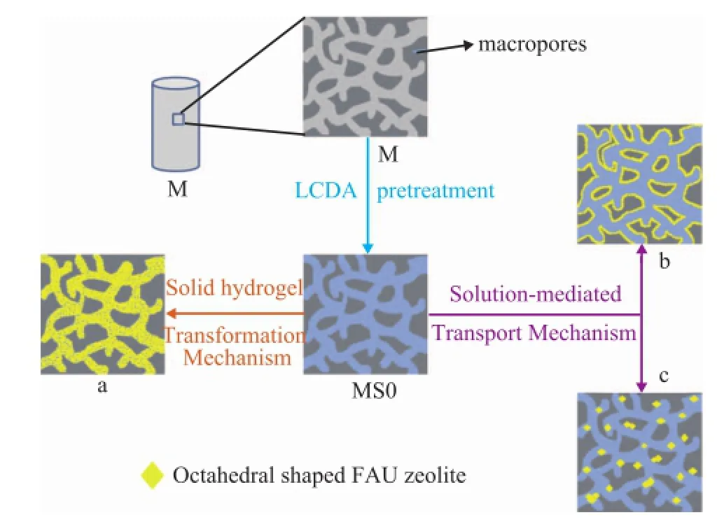
Figure 9 Schematic representation of FAU/composites with different morphology
4 Conclusions
Hierarchically trimodal-porous FAU composites with different morphology could be prepared by in-situ transformation of the pre-shaped macro-mesoporous γ-alumina monoliths via the LCDA induced hydrothermal method without any organic template or complicated ex-situ seeding procedure. The composition and the alkalinity of the precursor solution and the crystallization temperature appeared to have a critical effect on the morphology, porosity and deposition of the zeolite phase in the prepared composites. The resulted zeolite composites with varying morphology of aggregated zeolite clusters, zeolite layer or isolated zeolite crystals deposited on the walls of the well retained macroporous skeleton were obtained by easily adjusting the crystallization temperature.
The formation process was supposed as the “solid hydrogel–solution mediated transport mechanism”. The seed gel pretreatment of the γ-Al2O3substrate not only could produce zeolite/γ-Al2O3composites with hierarchically porous morphology, but also was the prerequisite for the formation of zeolite/γ-Al2O3composites through the pseudomorphic transformation. Furthermore, the presence of seed gel in the precursor solution was more favorable to inhibit the formation of impurity phases. It is evident that using a synthesis gel containing seeds can avoid any unnecessary ex-situ pretreatment of the support. This route not only illustrates a simple and green way to make zeolite coatings, but also provides a better understanding of in-situ synthesis. Since zeolite/alumina composites are in a monolithic form, it renders easier the shaping in an appropriate morphology for subsequent application. We anticipate that this efficient approach can be transferred to the synthesis of other hierarchical zeolite systems, thus providing a new generation of hierarchically porous materials with high surface areas and enhanced transport capabilities.
Acknowledgments: The authors are pleased to acknowledge the fnancial support from the National Natural Science Foundation of China (No. 20973022 and No. 11472048) and the State Key Laboratory of Catalytic Materials and Reaction Engineering (RIPP, SINOPEC) (Serial No. 33600000-14-ZC0607-0006).
[1] Li K, Valla J. Garcia-Martinez J. Realizing the commercial potential of hierarchical zeolites: New opportunities in catalytic cracking[J]. Chemcatchem, 2014, 6(1): 46-66
[2] Liu B Y, Chen F, Zheng L M, et al. Synthesis and structural properties of hierarchically structured aluminosilicates with zeolite Y (FAU) frameworks[J]. RSC Advances, 2013, 3(35): 15075-15084
[3] Parlett C M A, Wilson K.Lee A F. Hierarchical porous materials: Catalytic applications[J]. Chemical Society Reviews, 2013, 42(9): 3876-3893
[4] Lopez-Orozco S, Inayat A, Schwab A, et al. Zeolitic materials with hierarchical porous structures[J]. Advanced Materials, 2011, 23(22/23): 2602-2615
[5] Li X Y, Sun M H, Rooke J C, et al. Synthesis and applications of hierarchically porous catalysts[J]. Chinese Journal of Catalysis, 2013, 34(1): 22-47
[6] Yuan Y Y, Tian P, Yang M, et al. Synthesis of hierarchicalbeta zeolite by using a bifunctional cationic polymer and the improved catalytic performance[J]. RSC Advances, 2015, 5(13): 9852-9860
[7] Choi M, Na K, Ryoo R. The synthesis of a hierarchically porous BEA zeolite via pseudomorphic crystallization[J]. Chemical Communications, 2009(20): 2845-2847
[8] Tosheva L, Valtchev V P. Supported and self-bonded molecular sieve structures[J]. Comptes Rendus Chimie, 2005, 8(3/4): 475-484
[9] Ivanova S, Louis B, Madani B, et al. ZSM-5 coatings on beta-SiC monoliths: Possible new structured catalyst for the methanol-to-olefins process[J]. Journal of Physical Chemistry C, 2007, 111(11): 4368-4374
[10] Mori H, Aotani K, Sano N, et al. Synthesis of a hierarchically micro-macroporous structured zeolite monolith by ice-templating[J]. Journal of Materials Chemistry, 2011, 21(15): 5677-5681
[11] Wang Y J, Tang Y, Dong A G, et al. Zeolitization of diatomite to prepare hierarchical porous zeolite materials through a vapor-phase transport process[J]. Journal of Materials Chemistry, 2002, 12(6): 1812-1818
[12] Yu W, Yuan P, Liu D, et al. Facile preparation of hierarchically porous diatomite/MFI-type zeolite composites and their performance of benzene adsorption: The effects of NaOH etching pretreatment[J]. Journal of Hazardous Materials, 2015, 285: 173-181
[13] Saini V K, Pinto M L, Pires J. Characterization of hierarchical porosity in novel composite monoliths with adsorption studies[J]. Colloids and Surfaces: A - Physicochemical and Engineering Aspects, 2011, 373(1/3): 158-166
[14] Weh K, Noack M, Sieber I, et al. Permeation of single gases and gas mixtures through faujasite-type molecular sieve membranes[J]. Microporous and Mesoporous Materials, 2002, 54(1/2): 27-36
[15] Huang A, Wang N, Caro J. Seeding-free synthesis of dense zeolite FAU membranes on 3-aminopropyltriethoxysilanefunctionalized alumina supports[J]. Journal of Membrane Science, 2012, 389: 272-279
[16] Mohammadi T, Asarehpour S, Samei M. Effects of synthesis temperature and support material on CO2and CH4permeation through SAPO-34 membranes[J]. Separation Science and Technology, 2012, 47(16): 2320-2330
[17] Zhu G Q, Li Y S, Chen H L, et al. An in situ approach to synthesize pure phase FAU-type zeolite membranes: effect of aging and formation mechanism[J]. Journal of Materials Science, 2008, 43(9): 3279-3288
[18] Lang W Z, Ouyang J X, Guo Y J, et al. Synthesis of tubular faujasite X-type membranes with mullite supports and their gas permeances for N2/CO2mixtures[J]. Separation Science and Technology, 2011, 46(11): 1716-1725
[19] Sun G F, Liu Y, Yang J H, et al. Seeded synthesis of small polycrystalline NaY zeolite membrane using zeolite structure-directing agent and its pervaporation performance[J]. Journal of Porous Materials, 2011, 18(4): 465-473
[20] Burkat-Dulak A, Pashkova V, Pudlo W, et al. Nanomaterials with a multimodal pore structure based on the MFI-type zeolite[J]. Polish Journal of Chemistry, 2008, 82(9): 1809-1822
[21] Tokudome Y, Nakanishi K, Kosaka S, et al. Synthesis of high-silica and low-silica zeolite monoliths with trimodal pores[J]. Microporous and Mesoporous Materials, 2010, 132(3): 538-542
[22] Zamaro J M.Miro E E. Novel binderless zeolite-coated monolith reactor for environmental applications[J]. Chemical Engineering Journal, 2010, 165(2): 701-708
[23] Ping E W, Zhou R, Funke H H, et al. Seeded-gel synthesis of SAPO-34 single channel and monolith membranes, for CO2/CH4separations[J]. Journal of Membrane Science, 2012, 415: 770-775
[24] Yuan W, Yuan P, Liu D, et al. Novel hierarchically porous nanocomposites of diatomite-based ceramic monoliths coated with silicalite-1 nanoparticles for benzene adsorption[J]. Microporous and Mesoporous Materials, 2015, 206: 184-193
[25] Tan Q F, Bao X J, Song T C, et al. Synthesis, characterization, and catalytic properties of hydrothermally stable macro-meso-micro-porous composite materials synthesized via in situ assembly of preformed zeolite Y nanoclusters on kaolin[J]. Journal of Catalysis, 2007, 251(1): 69-79
[26] Vakifahmetoglu C. Zeolite decorated highly porous acicular calcium silicate ceramics[J]. Ceramics International, 2014, 40(8): 11925-11932
[27] Bonaccorsi L, Calabrese L.Proverbio E. Low temperature single-step synthesis of zeolite Y coatings on aluminium substrates[J]. Microporous and Mesoporous Materials, 2011, 144(1/3): 40-45
[28] Clet G, Jansen J C, van Bekkum H. Synthesis of a zeolite Y coating on stainless steel support[J]. Chemistry of Materials, 1999, 11(7): 1696-1702
[29] Wang Z, Al-Daous M A, Kiesel E R, et al. Design and synthesis of 3D ordered macroporous ZrO2/zeolite nanocomposites[J]. Microporous and Mesoporous Materials, 2009, 120(3): 351-358
[30] Zheng S Q, Gan J, Ren S, et al. Synthesis of Hierarchical Catalytic Materials From Si-Al Gel and Kaolin by Hydrothermal Crystallization[J]. Acta Petrolei Sinica (Petroleum Processing Section), 2014, 30(1): 32-37 (in Chinese)
[31] Pera-Titus M. Porous inorganic membranes for CO2capture: present and Prospects[J]. Chemical Reviews, 2014, 114(2): 1413-1492
[32] Chau J L H, Tellez C, Yeung K L, et al. The role of surface chemistry in zeolite membrane formation[J]. Journal of Membrane Science, 2000, 164(1/2): 257-275
[33] McLeary E E, Jansen J C, Kapteijn F. Zeolite based films, membranes and membrane reactors: Progress and prospects[J]. Microporous and Mesoporous Materials, 2006, 90(1/3): 198-220
[34] Nijhuis T A, Beers A E W, Vergunst T, et al. Preparation of monolithic catalysts[J]. Catalysis Reviews-Science and Engineering, 2001, 43(4): 345-380
[35] Sun M L, Zhao T B, Wang J, et al. Preparation of ZSM-5 coated on monolithic interconnected macroporous Al2O3using cheapn-butylamine as template[J]. Chinese Journal of Chemistry, 2015, 33(9): 1057-1063
[36] Lei Q, Zhao T B, Li F Y, et al. Catalytic cracking of large molecules over hierarchical zeolites[J]. Chemical Communications, 2006(16): 1769-1771
[37] Lei Q, Zhao T B, Li F Y, et al. Fabrication of hierarchically structured monolithic silicalite-1 through steam-assisted conversion of macroporous silica gel[J]. Chemistry Letters, 2006, 35(5): 490-491
[38] Lei Q, Zhao T B, Li F Y, et al. Zeolite beta monoliths with hierarchical porosity by the transformation of bimodal pore silica gel[J]. Journal of Porous Materials, 2008, 15(6): 643-646
[39] Xu X, Zhao T B, Qi J, et al. Micrometer-scale macroporous silica-alumina composites with spheric and lathy MFI-type crystals via seed-induced in-situ and layerby-layer synthetic methods[J]. Materials Letters, 2010, 64(15): 1660-1663
[40] Zhao T B, Xu X, Tong Y C, et al. The synthesis of novel hierarchical zeolites and their performance in cracking large molecules[J]. Catalysis Letters, 2010, 136(3/4): 266-270
[41] Zhao T B, Wang J, Xu X, et al. Preparation of hierarchically trimodal-porous ZSM-5 composites through steamassisted conversion of macroporous aluminosilica gel with two different quaternary ammonium hydroxides[J]. China Petroleum Processing & Petrochemical Technology, 2015, 17(1): 48-58
[42] Tong Y C, Zhao T B, Li F Y, et al. Synthesis of monolithic zeolite beta with hierarchical porosity using carbon as a transitional template[J]. Chemistry of Materials, 2006, 18(18): 4218-4220
[43] Bai P, Wu P P, Yan Z F, et al. A reverse cation-anion double hydrolysis approach to the synthesis of mesoporous gamma-Al2O3with a bimodal pore size distribution[J]. Microporous and Mesoporous Materials, 2009, 118(1-3): 288-295
[44] Tokudome Y, Fujita K, Nakanishi K, et al. Synthesis of monolithic Al2O3with well-defned macropores and mesostructured skeletons via the sol-gel process accompanied by phase separation[J]. Chemistry of Materials, 2007, 19(14): 3393-3398
[45] Cho K, Na K, Kim J, et al. Zeolite synthesis using hierarchical structure-directing surfactants: Retaining porous structure of initial synthesis gel and precursors[J]. Chemistry of Materials, 2012, 24(14): 2733-2738
[46] Han Q F, Bi F L. Introduction to Catalytic Materials[M]. Beijing: Chemical Industry Press, 2013: 53-56 (in Chinese)
[47] Tokudome Y, Nakanishi K, Kanamori K, et al. Structural characterization of hierarchically porous alumina aerogel and xerogel monoliths[J]. Journal of Colloid and Interface Science, 2009, 338(2): 506-513
[48] Xu R R, Pang W Q. Molecular Sieves and Porous Materials Chemistry[M]. Beijing: Science Press, 2004: 356-379 (in Chinese)
Received date: 2016-03-19; Accepted date: 2016-05-24.
Prof. Zhao Tianbo, Telephone: +86-13522293506; E-mail: zhaotb@bit.edu.cn.
- 中國煉油與石油化工的其它文章
- Removal of Nitrogen Compounds from Shale Diesel Fraction Using Ionic Liquid [C4mim]HSO4
- Puri fi cation of Aromatics over a PromisingCatalyst
- The Effect of Surfactant on Synthesis of ZSM-5 in a Super-Concentrated System
- Study on CO2Absorption by Aqueous Benzylamine and Its Formulations with Monoethanolamine as a Component for Post-Combustion Capture Process
- Effect of Magnetic Field on Tribological Properties of Lubricating Oils with and without Tricresyl Phosphate
- Improved Ti-containing Mesoporous Silica Catalyst Synthesized by Using Anionic Surfactant as Co-template

