Three-dimensional bistatic interferometric ISAR imaging
ZHAO Li-zhi(趙莉芝), MARTORELLA Marco, FU Xiong-jun(傅雄軍),, GAO Mei-guo(高梅國)
(1.School of Information and Electronics, Beijing Institute of Technology, Beijing 100081, China; 2.Department of Information, University of Pisa, Pisa 56122, Italy)
?
Three-dimensional bistatic interferometric ISAR imaging
ZHAO Li-zhi(趙莉芝)1, MARTORELLA Marco2, FU Xiong-jun(傅雄軍), GAO Mei-guo(高梅國)1
(1.School of Information and Electronics, Beijing Institute of Technology, Beijing 100081, China; 2.Department of Information, University of Pisa, Pisa 56122, Italy)
An approach based on interferometry technique is proposed for three-dimensional (3D) bistatic inverse synthetic aperture radar (ISAR) imaging. It is converted to a monostatic problem by using the theory that a bistatic radar equals a monostatic radar located on the bisector of bistatic angle. Then, interferometric phases extracted from a pair of cross shaped antennas are used to estimate the height and associated rotational velocity. Finally, numerical simulations are provided to evaluate this method.
bistatic inverse synthetic aperture radar (ISAR); 3D imaging; interferometric ISAR
Inverse synthetic aperture radar (ISAR) images have been widely used for target recognition. The conventional monostatic ISAR radar faces two threatens. One is that ISAR images cannot be obtained if the target moves toward the radar along the line-of-sight (LOS) direction without any rotation by itself. This situation sometimes happens since targets to be imaged are uncooperative. But for bistatic radar, this problem usually can be avoided due to the separated location of the transmitter and the receiver[1]. The other problem is that as an ISAR image is a two-dimensional (2D) projection of the target on the range-Doppler plane, it is not sufficient to interpret or identify target by referring the 2D ISAR images in some geometrical cases[2]. A feasible solution to this problem is to form three-dimensional (3D) ISAR images which provide the height information of each scattering center on a complex target as well as in radial range and cross-range[2]. Of course, the combination of the bistatic radar and 3D ISAR imaging technique can make full use of their merits. Hence, bistatic 3D ISAR has received much attention[3-9].
The purpose of this paper is to apply interferometric theory to form bistatic 3D ISAR images. In Ref.[4], an effective approach of interferometric 3D ISAR imagingwas proposed for monostatic radar. Based on the bistatic equivalent monostatic radar theory[1], this approach could be used in the bistatic case. In the paper, we find out how to use and improve the method presented in Ref.[4] to form bistatic 3D ISAR images. An appropriate system configuration has been given, which uses four receiver antennas to form two orthogonal base lines. Assume that we can adjust the position of four antennas arbitrarily to make sure the horizontal baseline lie on the plane including the transmitter, the receiver and the target. Finally, the height information of the target is obtained by exploiting the interferometric phases, and the range scaling is achieved by using the information of the four ISAR images to estimate the effective rotation angle firstly.
1 Bistatic radar signal model
1.1 Interferometric bistatic radar system geometry
The radar system is depicted in Fig.1, whereTdenotes a transmitter andRrepresents a receiver equipped with four antennas (AV,BV,AHandBH). A local Cartesian coordinateTξ(ξ1,ξ2,ξ3) is defined, where the originOis the target rotation center, both the axisξ1and the axisξ2are located on theOTRplane, andξ2is along the bisector line of the bistatic angle ∠TOR. The four antennas form two orthogonal lines.AVandBVare placed on the vertical line paralleled with the axisξ3.AHandBHare disposed on the horizontal line perpendicular with the lineOR. Moreover,AHandBHare constrained on theOTRplane.
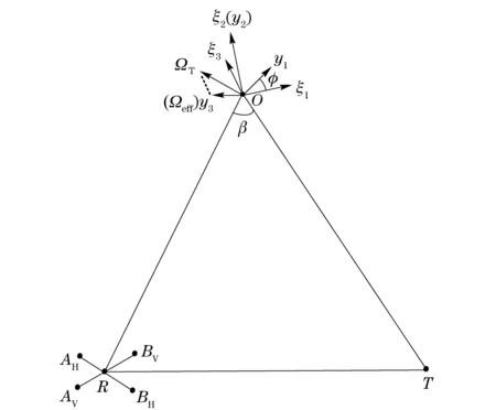
Fig.1 Interferometric bistatic radar geometry
In a bistatic ISAR scenario, a target may experience several kinds of rotation, such as roll, yaw, pitch, and rotation induced by translational motion. We use a total rotation vectorΩT(t) to replace all kinds of rotational combinations. Since the ISAR integral time is short, one can considerΩT(t) as a constant. Then the effective vectorΩeffis the projection of the vectorΩT(t) onto the planeξ1Oξ3.
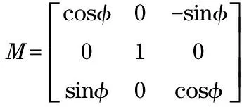
To describe the position of each reflective scatterer located at the target, a coordinate systemTx(x1,x2,x3) is defined. The axisx1is along the cross range direction. The axisx2which is consistent with the axisξ2directs the radial range. The axisx3leads to the height range direction, which is arranged to the direction of the effective vectorΩeff. From Fig.1, it is worthy noticing thatTξrotates clockwise an angleφwith respect toTx. Therefore, theTξcan be described as
Tξ=MTx
(1)
where the rotation matrixMxξis
(2)
By referring to Ref.[8], the location of a generic scatterer can be expressed as
x(t)=y+ct=(y1+c1t)ix1+(y2+c2t)ix2+(y3+c3t)ix3
(3)
wherex(0)=y, andc=ΩT×y.
1.2 Received signal
The form of the received signal depends on the radar-target geometry and the transmitted waves. Herein,Txis taken as the global reference system, and stepped frequency waves are used. The received signal from a point scatterer, in time-frequency domain, can be written as
(4)
(5)
whereρdenotes the reflectivity of the scatterer;ilos-Tis LOS unit vector from the transmitterTto the target;ilos-ijis the LOS unit vector from one receiver antenna to the target,i∈[A,B] andj∈[V,H];f0is the carrier frequency;Bwis the transmitted bandwidth;Tobsis the coherent processing time. After bistatic radial motion compensation, the received signal can be represented by
(6)
Applying the theory that bistactic radar can be replaced by an equivalent monostatic from signal processing aspect, Eq.(6) can be rewritten as
(7)
whereβijis the bistaic angle correspond to each antenna. Letβdenote the angle ∠TOR,θdenote the angle ∠AHOR, andddenote the length ofAHBH(orAVBV). Thenβijandiijcan be expressed as
βAV=βBV=β,βAH=β-θ,βBH=β+θ
(8)
(9)
(10)
After 2D FFT, the ISAR image can be obtained, which is
(11)
whereK0ij=y·iij,K1ij=c·iij. The detailed descriptions are:
(12)
(13)
Due tod?RR, ISAR images produced from the returns of the four antennas are nearly identical.
2 3D target reconstruction
2.1 Height estimation
The height information is carried by the interferometric phases. Hence, we analyze the expressions of phase differences for each scatterer. Before that, all the dominant scatterers are extracted from the four ISAR images using the CLEAN technique[9]. Then, the phase differences can be calculated as
(14)
(15)
Thus, the coordinates of a generic scatterer with respect toTx(x1,x2,x3) can be expressed as
(16)
(17)

2.2 Parameter estimation
The angleφand the effective rotation velocityΩeffcan be estimated by exploiting the Doppler information of scatterers. Here, the componentc2ofcplays an important role. SinceΩT=0ix1+ΩT1ix2+Ωeffix3andc=ΩT×y,c2can be derived as
c2=Ωeffy1
(18)
Meanwhile, reviewing Eqs.(11)(13),c2can also be described as
(19)
Then, substituting Eq.(16) and Eq.(19) into Eq.(18), we obtain:
(20)
By defining the following quantities:
(21)
Eq.(20) can be rewritten as
ZaX+bY
(22)
It can be seen thatφandΩeffcan be obtained by firstly estimatingaandb. The estimation ofaandbcan be considered as a statistical estimation problem. Assume that there areKbright scatterers in the ISAR images. Then,Z,XandYbecome threeK×1 vector, namelyZ=(Z1,Z2,…,ZK)T,X=(X1,X2,…,XK)T, andY=(Y1,Y2,…,YK)T. Using the least-squares estimation (LSE), the results are
(23)

(24)
(25)
At this point, we can obtain the height information. In addition, we also can get the cross range scaling factor with the knowledge ofeff, which is shown as
(26)
3 Simulations
A simulation has been done by referring to the configuration plotted in Fig.1 and using the parameters in Tab.1. The frequency number is 256 and the sweep number is 128. The target is supposed to be rotating along a fixed vector without translational moving. Therefore, the bistatic angle is a constant during the observation time.

Tab.1 Simulation parameters
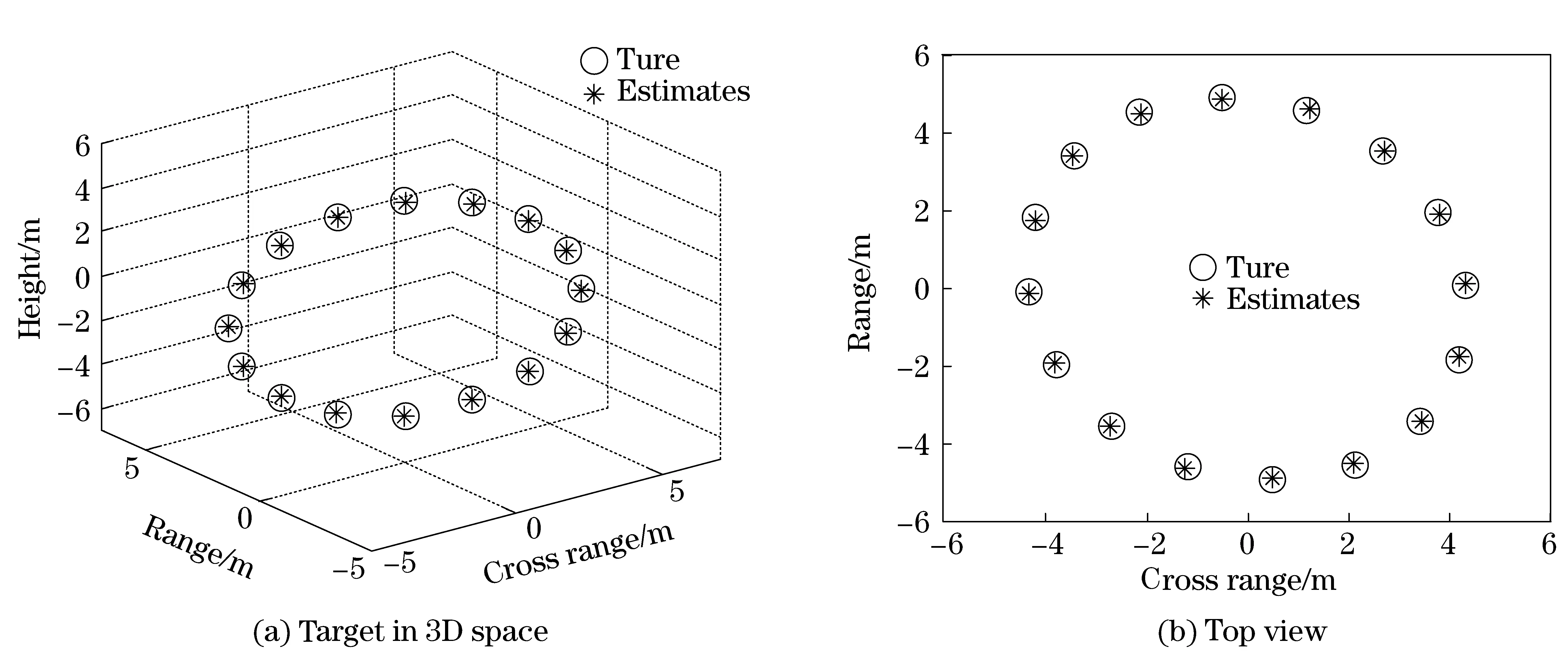
The received signal has been simulated for several values of the signal noise ratio (SNR). In Fig.2a, it shows the 3D image of the target when SNR is 0dB. The target consists of 16 scatterers, and these points are uniformly distributed on a circle in the 3D space. From Fig.2b-Fig.2c, we can see the target’s projections onto the three coordinate planes. After running 100 Mento Carlo simulations, the mean square error of height’s estimates is produced, which is illustrated in Fig.3. As expected, the height error decreases when the SNR increases.
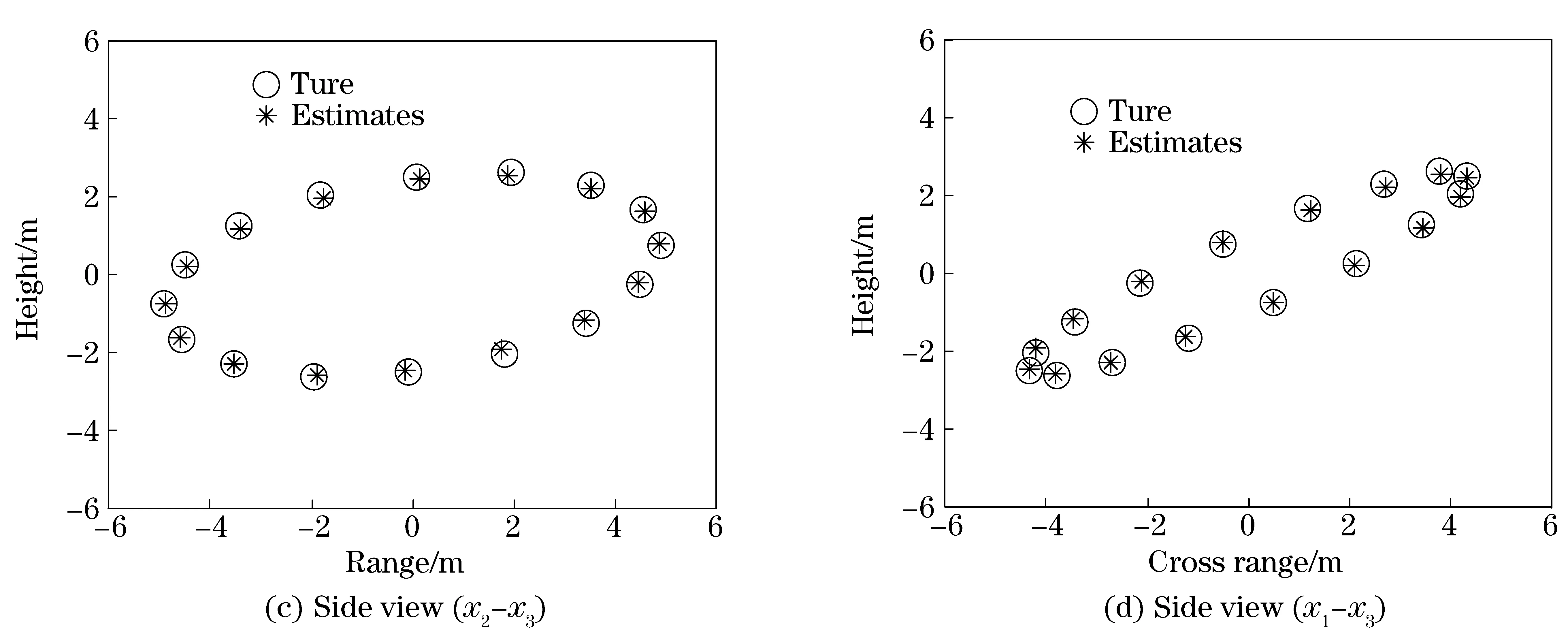
Fig.2 3D image of the target and three different projected views using interferometric bistatic radar (SNR=0 dB)
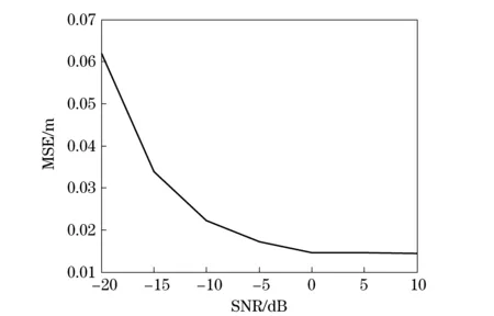
Fig.3 Mean square error of the height estimation
4 Conclusion
This paper demonstrated a novel method for bistatic 3D imaging, which use four interferometry 2D ISAR images. Meanwhile, we estimated target effective rotation velocity to scale the cross range. Simulation results showed the effectiveness of the approach. Since the horizontal antennas are constrained on the same plane with transmitter, receiver and target, the future work should focus on improving the algorithm in a general case.
[1] Martorella M, Palmer J, Homer J, et al. On bistatic inverse synthetic aperture radar[J]. IEEE Trans on Aerospace and Electronic System, 2007, 43(3): 1125-1134.
[2] Martin D F, Gonzalez J T, Garcia M B. Interferometric ISAR imaging on maritime target applications: simulation of realistic targets and dynamics[J]. Progress in Electromagnetics Research, 2012, 132: 571-586.
[3] Ma Changzheng, Tat Soon Yeo, Guo Qiang, et al. Bistatic ISAR imaging incorporating interferomteric 3-D imaging technique[J]. IEEE Trans on Geoscience and Remote Sensing, 2012, 50(10): 3859-3866.
[4] Battisti N, Martorella M. Interferometric phase and target motion estimation for accurate 3D reflectivity reconstruction in ISAR system[C]∥2010 IEEE Radar Conference, Washington, USA, 2012.
[5] Xu Xiaojian, Narayanan R M. Three-dimensional interferometric ISAR imaging for target scattering diagnosis and modeling[J]. IEEE Trans on Imaging Processing, 2001, 10(7): 1094-1102.
[6] Kempf T, Peichl M, Dill S, et al. 3D tower-turntable isar imaging[C]∥2007 European Radar Conference, Munich, Germany, 2007.
[7] Suwa K, Yamamoto K, Iwamoto M, et al. Reconstruction of 3-D target geometry using radar movie[C]∥2008 Eroupean Conference on Synthetic Aperture Radar, Friedrichshafen, Germany, 2008.
[8] Berizzi F, Mese E D, Martorella M, et al. High resolution ISAR imaging of maneuvering targets by means of the range instantaneous doppler technique: modeling and performance analysis[J]. IEEE Trans on Image Processing, 2001, 10(12): 1880-1890.
[9] Martorella M, Acito N, Berizzi F. Statical CLEAN technique for ISAR Imaging[J]. IEEE Trans on Geoscience and Remote Sensing, 2007, 45(11): 3552-3558.
(Edited by Cai Jianying)
10.15918/j.jbit1004-0579.201524.0115
TN 958.8 Document code: A Article ID: 1004- 0579(2015)01- 0105- 05
Received 2013-10- 07
E-mail: fuxiongjun@bit.edu.cn
 Journal of Beijing Institute of Technology2015年1期
- Journal of Beijing Institute of Technology的其它文章
- Numerical simulation of the delay arming process of initiating explosive brakes
- Optimized design of biconical liner by orthogonal method
- Wideband acoustic source localization using multiple spherical arrays: anangular-spectrum smoothing approach
- Influence of eddy current on transient characteristics of common rail injector solenoid valve
- Designing the cooling system of a hybrid electric vehicle with multi-heat source
- Novel miniature pneumatic pressure regulator for hopping robots
