An analysis of dam-break flow on slope*
WANG Li-hui (王立輝)
College of Civil Engineering, Fuzhou University, Fuzhou 350108, China, E-mail: wlh0411@hotmail.com
PAN Cun-hong (潘存鴻)
Zhejiang Institute of Hydraulics and Estuary, Hangzhou 310020, China
An analysis of dam-break flow on slope*
WANG Li-hui (王立輝)
College of Civil Engineering, Fuzhou University, Fuzhou 350108, China, E-mail: wlh0411@hotmail.com
PAN Cun-hong (潘存鴻)
Zhejiang Institute of Hydraulics and Estuary, Hangzhou 310020, China
(Received September 9, 2013, Revised January 13, 2014)
The one-dimensional steep slope shallow water equations are used to model the dam-break flow down a uniform slope with arbitrary inclination, and analytical solutions are derived by the hodograph transformation and the Riemann?s method in terms of evaluated integrals. An implicit analytical solution is obtained to evaluate the spatio-temporal distributions of dam-break flood hydrographs along the slope. For convenience, the solution for representative wave profiles and velocity distributions is shown in charts. Comparing with the Dressler?s solution and WES experimental data, the analytical solution is seen reasonable.
dam-break flow, slope, hodograph transformation, Riemann?s method
Introduction
The failure of dams and the resulting flows would occur with little warning and may result in a substantial damage to life and property. The velocity and the depth of the dam-break flood wave usually decrease along a river reach. Recently, the time and the distance forecasting about the dam-breach flood waves received a considerable attention in literature. Many attempts[1]were made to simulate the dambreak flood behaviors with the shallow water equations. Leveque[2]simulated the dam-break numerically with several algorithms. Zoppou and Roberts[3]presented a comparison of a range of solvers for one-dimensional unsteady flow. Macchione and Morelli[4]tested new numerical schemes with dam-break simulations. These computational models aim to calculate the front of the motion due to steep gradients (discontinuities, or the motion of the broken waves) and the diminishing heights (an unsteady interface between wet/dry regions), but there are numerical instabilities and significant errors during the simulations. These problems are caused by two reasons, one is the model formulation can not reflect the complex flow phenomena, and the other is the shortcoming of the numerical algorithms. It is important to obtain the exact analytical solutions for the dam-break flow along steep slopes, to be used to test the robustness of numerical schemes.
For the dam-break problem on a horizontal bed, under the hypothesis of instantaneous dam-break in a horizontal rectangular channel, Ritter (1892) derived an analytical solution for the dam-break flow with the Saint-Venant equations, in which the bottom slope and the frictional effects were neglected. Hogg and Pritchard[5]theoretically investigated the effects of resistive forces on unsteady shallow flows over rigid horizontal boundaries, and obtained a first-order correction for resistance effects for the dam-break wave propagation with the perturbation method. Adduce et al.[6]obtained the solution of the dam-break problems with the hodograph transformation and the characteristics method. Goater and Hogg[7]developed an analytical solution for a dam-break flow of a finite reservoir into a tailwater using the hodograph transformation of the governing equation to model the unsteady flows.
For a sloping bed, most dam-break solutionswere obtained with the simplified shallow-water equations, neglecting the inertia or pressure-gradient terms in equations. Hunt developed a kinematic wave approximation for the dam failure in a dry sloping channel and verified the solution by computing the orders of magnitude of the neglected terms. Huang et al.[8]presented an analytical model for one-dimensional dambreak flood on a sloping channel bed with the characteristics method. By employing the kinematic wave approximation, the asymptotic solutions for the dambreak were analyzed[9,10], in which the shallow-water equations were transformed into a single nonlinear diffusion equation based on the conservation of mass and momentum. Exact solutions of the shallow-water equations were obtained for infinite-volume dambreak floods on a sloping bed, using the hodograph transformation and characteristics methods[6,11-13].

Fig.1 Definitions in the dam-break model on slope
The solutions for the dam-break are derived with analytical techniques to exploit the characteristic structure of the Saint Venant equations. In simple wave regions where the characteristic lines are straight, the solution is easily obtained for the dam-break, tracking simply the evolution along the characteristic curves. In other regions where the characteristic lines are not straight, for solving the problem, we employ the hodograph transformation, which converts the nonlinear shallow-water equations into a linear system by exchanging the roles of the dependent and independent variables, and then the analytical solutions are constructed with the Riemann?s method. The treatments are adopted by many authors to study frictionless inertial flows[6,13]and the bore flows up inclined boundaries[11]. However, the flows were in unbounded domains with idealized initial conditions in those studies. In the finite sloping reservoir, the influence of the endwall on the motion in the flume is rather strong, including the bores of the dam-break wave. More sophisticated mathematical techniques are required for the constructions of the solutions.
In this paper, a new analytical solution is obtained for the dam-break flow over a finite reservoir without friction on the sloping bed. The paper is organized as follows. Firstly, the dam-break problem is formulated and the key dimensionless parameter is identified, which is proportional to the depth of the reservoir. Secondly, the Riemann function for the dambreak is constructed with the characteristic line method, identifying regions where the characteristic variables are constant or varying, determining the initial and boundary conditions for the dam-break problem, and transforming the governing equations into the hodograph form. Thirdly, the dam-break analytical solution is constructed, using the characteristics method and the Riemann function to represent the flow. Fourthly, the analytical solutions are discussed in detail, and compared with the Dressler?s solution and the WES experimental data. Finally, the conclusions are given.
1. Dam-break governing equations
1.1Model for dam-break flood over bed slope
The one-dimensional steep-slope shallow water equations are applied with some suitable approximations for modeling the dam-break over a wide, uniformly sloping bed inclined at an angleγwith respect to the horizontal direction (Fig.1). Neglecting the bed friction effect, these equations can be written as

whereh*is the depth of the dam-break flow,u*is the depth-averaged flow velocity,gis the magnitude of gravitational acceleration,γis the dam-break flood over the angle of the channel bed,x*is the downstream coordinate,t*is the time.
Equations (1)-(2) can be normalized with the following non-dimensional variables
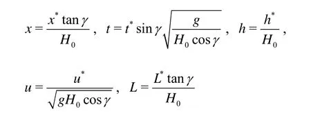
whereH0is the initial fluid depth at the dam site. Substituting the above non-dimensional variables into Eqs.(1) and (2), we can get the following non-dimensional equations

As shown in Fig.1, the reservoir is located at the left side of the vertical dam, and the reservoir geometry is defined by the triangle OFB on the slope, where OB is the dam wall. The initial conditions are

1.2Model for the dam-break problem
Numerical methods are generally adopted to solve the equations, however, special procedures are required to deal with the moving boundary at the wet/ dry front. Rewriting Eqs.(3) and (4) in the characteristic form, the numerical scheme may be developed without a special consideration of the wet/dry front. With the local long wave celerityC=, Eqs.(3) and (4) can be written as[14]
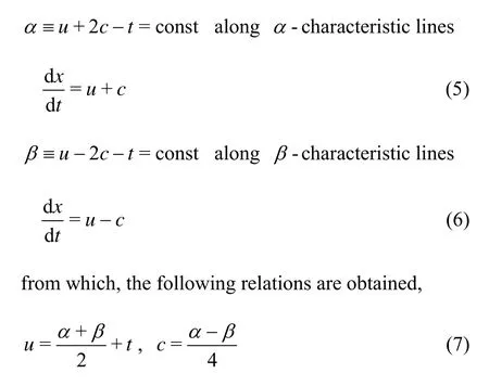
2. The hodograph transformation and dam-break problem analysis
2.1Hodograph transformation
Due to the nonlinear terms in Eqs.(3) and (4), it is difficult to solve these equations with an explicit method. The next step is the linearization in order to use analytical methods available for linear partial differential equations. The governing equations are transformed into quasi-linear equations, using the independent hodograph variablesαandβinstead ofxandt[15]. The characteristic forms of the governing Eqs.(5) and (6) become

With the new variables and Eq.(7), the homogeneous Eqs.(8) and (9) are reduced to

The hodograph transformation remains invertible provided the Jacobin of the transformationJremains finite and non-vanishing. By using Eqs.(8) and (9), it is possible to show that

The transformation is reversible providedJ≠0 andJ-1≠0. This condition is satisfied here except at the flow boundaries, but where the solution is known (as summarized in Table 1), and this restriction presents no difficulty.
Equation (10) is a second-order linear hyperbolic partial differential equation, of which the solution can be evaluated in terms of Riemann functions[16]. The boundary conditions for the equation will be specially discussed in the next section.
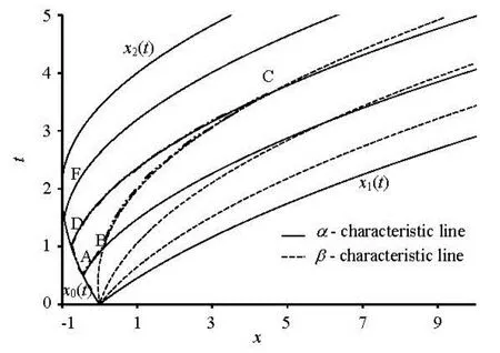
Fig.2 Characteristic line in (x-t) plane

Table 1 The boundary conditions of the dam-break problem
2.2Dam-break problem analysis
To solve Eq.(10), it is necessary to determine the boundary conditions for the dam-break problem in Fig.2. When the dam is instantaneously collapsed (t= 0+), a part of the water immediately moves downstream in the form of a forward wave, while a wave propagating upstream separates the moving fluid from the static fluid upslope. The downstream and upstream waves constitute the moving boundaries issuing from the origin point inx-tplane. One boundary corresponds to the flow front, the other constitutes the locus of the upstream propagating wave from Point F (Fig.2). The boundaries can be described mathematically by the characteristic lines inx-tplane, which can be computed using Eq.(5) or Eq.(6), withh=0 (forward front) andu=0 (backward wave).
For the forward front, a front curvex=x1(t) is generated after the dam-break, which is defined as the curve separating the wet/dry parts along the sloping plane on the downstream. Withh=0 (forward front), Eq.(5) reduces to dα/ dt=d(u-t) /dt=0. The initial condition[13]ist=0=2. Use of this value as the initial condition in d(u-t) /dt=0 yields the front velocity solutionu=t+2. This interface is deduced from the fluid velocity to satisfy the kinematic conditions dx1(t) /dt=u=t+1, and it is shown thatx1(t) =t2/2+2tis the locus of the front position inx-tplane. Furthermore, at the front, the height vanishes (c=0) and so we can rewrite the kinematic condition asx˙=α+t. Note also that along the front curve we haveα=β.
The conditionα=βimplies that, similar to the dam break on a horizontal plane, a rarefaction fan (Fig.2) is generated as long as the right rigid wall is removed. Indeed, att=0-andx=0, the values of the characteristic variables areα=2 andβ=-2. When the right rigid wall is removed (t=0+), a front curve[13]is generated along whichα=β=2. This means that att=0+andt=0-the Riemann invariantβhas to vary continuously between -2 and 2 and consequently a fan ofβ-characteristic lines is generated atx=0. However, in contrast to the solution for the horizontal plane, such a fan is not associated with a simple wave region, because in the adjoining region associated with the initial conditions, the characteristic variablesαandβdo not take constant values.
For the backward wave, Eq.(6) reduces to d(- 2c-t) /dt=0 along the characteristic line dx0(t) /dt=u-cwithu=0 (backward wave), which means that the wave is propagating upstream from the dam into the still water. Integration of this equation givesc= -t/ 2+1, with the initial conditiont=0=1. With the substitution of this result into the equation defining the characteristic line, dx0(t) /dt=u-c=t/ 2-1, it is shown thatx0(t) =t2/4-tis the backward wave inx-tplane. So, the backward wave reaches Point F in Fig.2 at timetb=2.

Based on all above analyses, the boundaries of the dam-break problem can be defined, and Figure 2 illustrates the position of the boundaries inx-tplane, as listed in Table 1.
Compared with the horizontal plane, the sloping plane sees some differences (Table 1). First, the forward front propagates down the slope with a same acceleration along the slope, which is issued from the origin or Point F. Second, the speed of the advancing flow front always exceeds that of the advancing tail aftert≥tF. The difference in speeds implies that the traveling wave of fluid continuously elongates at a constant rate. Of course, it would not occur in a real dam-break flow with a frictional function.
3. Riemann formulation
To solve the Riemann?s formulation (10), an adjoint differential operator is introduced:

With Eq.(10) and adjoint operator (12), the Green?s formula takes the form

Using an integral representation to relatetto its auxiliary conditions, Eq.(13) can be integrated over a finite domainΩ, in which the oriented contour is denoted byS. Indeed, if these area integralsΩcan be transformed into boundary integralsSusing the Green?s theorem, a part of Eq.(10) can be solved.
Since the adjoint differential functionM[]τis chosen freely, one may let

In this case, the solution of Eq.(14) to satisfy these boundary conditions can be written as the Riemann functionR(r,s;a,b)

WhereF[] is the hypergeometric function. According to the Riemann method, a functiont(ξ,η) satisfies (10), if and only if the linear differential formω=τL(t) -tM(τ) is exact. For all regular domainsΩin (α,β) plane, it is required that

whereSrepresents the boundary ofΩ.
With the boundary conditions in Table 1, the Riemann?s method is applied to construct the solution on the region ABCD bounded by characteristic lines (Fig.2). The curve AD is made by theβ-characteristic line, and BC is aβ-characteristic line inside the fan area. The curves AB and CD areα-characteristic lines in the fan area. The coordinates of the Points A, B, C, D are given in the hodograph plane

where 1αis the value carried by theα-characteristic line along the line AB. From the Riemann construction[12]in Eq.(19) with = (,;,)RR a bα β, we obtain
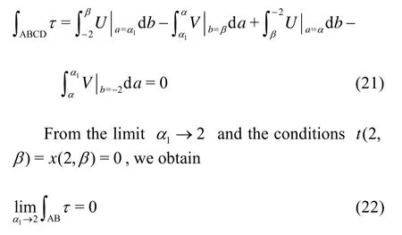
The second integral in (21) can be computed from the boundary conditions (15)-(17). Integrating by parts and the subsequent evaluation asα1→2 yield

The third integral of (21) can be also evaluated from the boundary conditions (15)-(17) and the integration by parts,

The expression includes the contribution from the curve, along whicht(α,-2 )=α/ 2 - 1 is given by Table 1 and Eq.(5). It also permits the evaluation of the final contribution in Eq.(21)
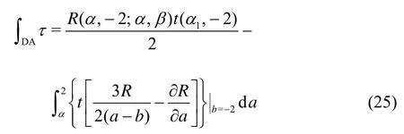
Collecting all the contributions (22)-(25) together, the further integration by parts yields the result for the time field within the fan

Giving this parametric expression for the timetas a function of the hodograph variablesαandβ, it is straightforward to findx(α,β) by integrating the equation along characteristic line (8) or (9). And then from the characteristic line (8) and the conditionst(2,β) =0 andx( 2,β) =0, we obtain

in which the boundary conditionxt=0=0 has been taken into account.
Although the expressions of Eqs.(26) and (27) are not fully explicit, these exact integral solutions can be evaluated with a numerical method, which will be discussed in the next section.
With Eqs.(26) and (27), the dam site dimensionless depth and velocity hydrographs can be obtained forx=0. After the dimension transform, the original hydrographs are used as the upstream boundary condition in routing of flood downstream.
4. Discussion of the results
4.1Synthesis of the results

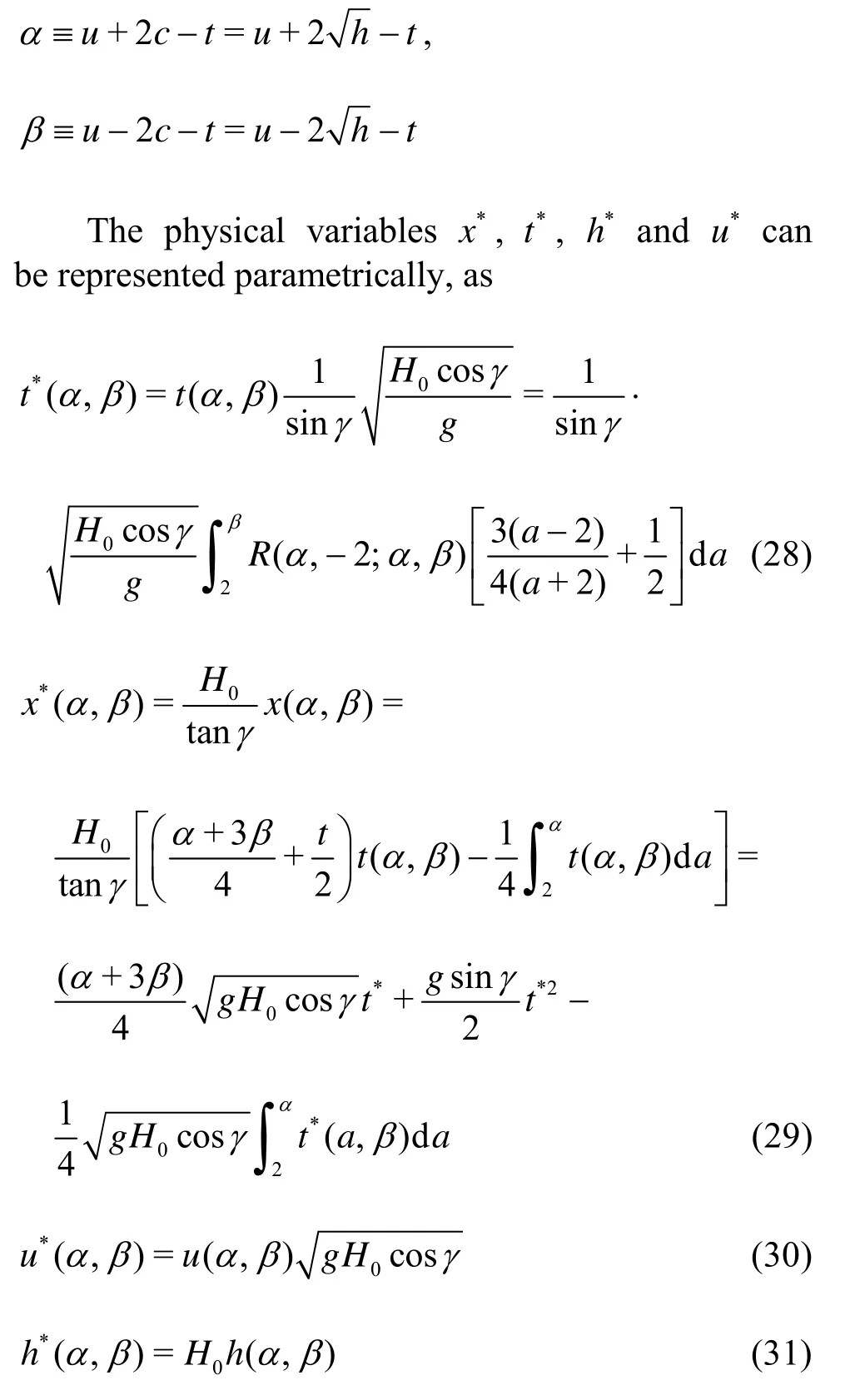
Ifα>β>-2 and -2 <α< 2,R(a,-2;α,β) is given by Eq.(18).
Ifβ=-2 and -2 <α< 2, the backward wave boundary conditions are applied within 0<t<tF, andwe have,
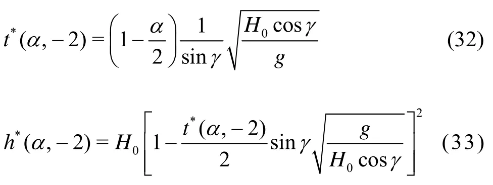
Ifα=2 andβ>-2, the dam break solution returns to the initial condition before the dam breaks.
Ifα=β=2 , the position and the velocity of the flood front can be given.
Ifα=βandα>-2, it corresponds tot→∞, the solution has no particular physical meaning.
Ifα=β=-2, the position and the velocity of the flow tail after the fluid has detached from Point B (Fig.2, fort>tF),

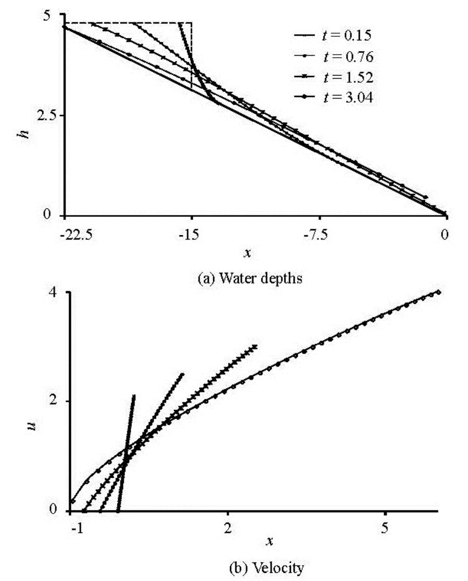
Fig.3 The analytical solution in the original coordinatexalong the sloping bed
Figure 3 shows the evolution of the water-depthh*profiles and the velocityu*at different times after the dam collapse, in the original coordinatexalong the sloping bed (γ=12o). The wave?s shape and the velocity distribution are shown in Fig.3, in terms ofh*andu*fort=0.15, 0.76, 1.52 and 3.04. The flow depth profile is symmetric increasingly with the time in Fig.3(a). As shown in Fig.3(b), the velocity distribution is almost linear for these smallt-values. Beforet=2tan-1γ(t=3.04), the part of water still remains undisturbed in the reservoir.
From the velocity and flow depth profiles at early times, it is possible to evaluate the discharge hydrograph at the dam site, which can be used as the boundary conditions in the routing flood downstream.
The depth profiles and the velocity distributions for largert-values are shown in Fig.4 and Fig.5. Due to the quick elongation and flattening of the water profile, the quantitiesx/tandhtare used to scale the profile at the horizontal and vertical directions, separately. The position of the maximum height of the dam-break wave is located at the middle of the moving mass of water, and with time, this position moves toward the centre of the wave.

Fig.4 Water depths in the original coordinatex/talong the sloping bed > (γ=12o)
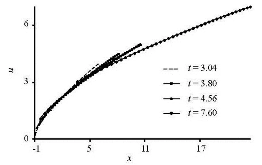
Fig.5 The velocity in the original coordinatexalong the sloping bed (γ=12o)
Att=2tan-1γ(γ=12o), the disturbance of the back wave reaches the tail end of the reservoir. Fort> 2tan-1γ, the left-hand limit of the water movesdown the slope. Figures 4 and 5 shows the profiles and the velocity distributions fort=3.04, 3.80, 4.56 and fort=7.6. Whent=7.6, the upstream limit of the water has moved tox=3.6. For clarity, the vertical scale for the depthhhas been stretched five times as indicated. With these larget-values, the velocity distribution becomes more non-linear in the upstream region, and the moving mass of water quickly elongates and flattens. Of course, the real profile depth and velocities are not elongated and flattened so quickly due to the friction term.
4.2Comparing with Dressler result
Dressler (1958) obtained an approximate expression for the dam-break ofh(t) on the dam site[17,18]
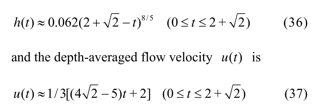
The comparison between our analytical results and the Dressler?s solutions for depth and velocity hydrographs at the dam site are shown in Figs.6 and 7, from which a good agreement is seen.
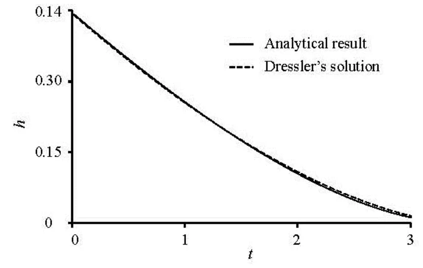
Fig.6 The analytical result and Dressler?s solution depth hydrographs on the dam site

Fig.7 The analytical result and Dressler?s solution velocity hydrographs on the dam site
4.3Comparison with experimental data
Experimental measurements of dam-break flood waves on the slope channels are relatively few in literature. In this section, we will validate the analytical solution with the laboratory experiments for dam break in sloping channels conducted by the U.S. Army Corps of Engineers Waterways Experiment Station[19,20](WES, 1960). The set of experiments is particularly interesting because it is under conditions of minimum resistance, close to those of the analytical solution of dam-break without friction in this paper.

Fig.8 The comparison of analytical solutions and measured (WES) data
The experiments were carried out in a wooden rectangular flume, with Manning?snequal to 0.009. The flume is 4 ft wide and 400 ft long with a slope 0.005, and the dam is located at the middle of theflume. The dam was suddenly removed with an initial water level of 1 ft at the upstream side. Observations for stage-time hydrographs were made both upstream and downstream of the dam, so providing experimental data on the reservoir emptying process that can be numerically reproduced.
Due to space limitation, here we focus our attention on experiment 1.1of WES, characterized by the initial dry bed condition and the full depth breach with an instantaneous dam-break model. Figure 8 shows the comparison between measured and analytical solutions for stage-time hydrographs at distance of 195 ft, 200 ft and 220 ft from upstream.
The comparisons between the analytical and experimental flow stages at the different locations are shown in Fig.8, from which it is seen that the analytical results are consistent with experimental data. Due to the absence of friction terms in our analytical solution of the shallow water equations, the difference between the experimental data and analytical solution is reasonable.
5. Conclusions
Based on the one-dimensional steep-slope shallow water equations, an analytical solution for the dam-break problem on a sloping plane is derived in a dimensionless form, by using a hodograph transformation, the Riemann?s function method and some analytical techniques. From the analytical examples, even though the friction term is not considered, our robust analytical solution enjoys a reasonable agreement with the known theoretical and experimental results in the simulation of the dam-break wave propagation without friction.
The elementary features of the dam-break wavefront and the back wave characteristic curves are obtained directly from Riemann characteristic forms for the shallow-water equations. Such as, the forward fronts propagate down slope with a same acceleration along the slope, from the origin or Point F. The speed of the advancing flow front from the origin always exceeds that of the advancing tail aftert≥tF. The difference in the velocity implies that the traveling wave of fluid continuously elongates at a constant rate, which does not appear in a real dam-break flow with frictions.
Finally, the results are compared with the Dressler?s solutions and WES experimental results, and the analytical solution is seen reasonable.
There are still further interesting developments with more complex dam-break models, such as the dam-break flow with tailwaters, and the dam-break flow in cascade reservoirs with a steep bottom slope.
[1] SHIGEMATSU T., LIU P. L. F. and ODA K. Numerical modeling of the initial stages of dam-break waves[J]. Journal of Hydraulic Research, 2004, 42(2): 183-195.
[2] LEVEQUE R. J. Finite volume methods for hyperbolic problems[M]. Cambridge, UK: Cambridge University Press, 2002.
[3] ZOPPOU C., ROBERTS S. Explicit schemes for dambreak simulations[J]. Journal of Hydraulic Engineering, ASCE, 2003, 129(1): 11-34.
[4] MACCHIONE F., MORELLI M. A. Practical aspects in comparing shock-capturing schemes for dam break problems[J]. Journal of Hydraulic Engineering, ASCE, 2003, 129(3): 187-195.
[5] HOGG A. J., PRITCHARD D. The effects of hydraulic resistance on dam-break and other shallow inertial flows[J]. Journal of Fluid Mechanics, 2004, 501: 179-212.
[6] ADDUCE C., SCIORTINO G. and PROIETTI S. Gravity currents produced by lock exchanges: Experiments and simulations with a two-layer shallow-water model with entrainment[J]. Journal of Hydraulic Engineering, ASCE, 2011, 138(2): 111-121.
[7] GOATER A. J. N., HOGG A. J. Bounded dam-break flows with tailwaters[J]. Journal of Fluid Mechanics, 2011, 686: 160-186.
[8] HUANG Guo-fu, WU Chao and ZHANG Yi-fei et al. Analytical solutions for 1-D dam-break flood on sloping channel bed[J]. Journal of Hydrodynamics, 2005, 20(5): 597-603.
[9] ANCEY C., COCHARD S. The dam-break problem for Herschel-Bulkley viscoplastic fluids down steep flumes[J]. Journal of Non-Newtonian Fluid Mechanics, 2009, 158(1): 18-35.
[10] CHANSON H. Analytical solutions of laminar and turbulent dam break wave[C]. International Conference on Fluvial Hydraulics River Flow. Lisbon, Portugal, 2006, 1: 465-474.
[11] BALDOCK T. E., HUGHES M. G. and DAY K. et al. Swash overtopping and sediment overwash on a truncated beach[J]. Coastal Engineering, 2005, 52(7): 633-645.
[12] ANTUON M., HOGG A. J. Run-up and backwash bore formation from dam-break flow on an inclined plane[J]. Journal of Fluid Mechanics, 2009, 640: 151-164.
[13] ANCEY C., IVERSON R. M. and RENTSCHLER M. et al. An exact solution for ideal dam-break floods on steep slopes[J]. Water Resources Research, 2008, 44(1): 1-10.
[14] FERNANDEZ-FERIA R. Dam-break flow for arbitrary slopes of the bottom[J]. Journal of Engineering Mathematics, 2006, 54(4): 319-331.
[15] DELESTRE O., LUCAS C. and KSINANT P. A. et al. SWASHES: A compilation of shallow water analytic solutions for hydraulic and environmental studies[J]. International Journal for Numerical Methods in Fluids, 2013, 72(3): 269-300.
[16] MANGENEY A., HEINRICH P. and ROCHE R. Analytical solution for testing debris avalanche numerical models[J]. Pure and Applied Geophysics, 2000, 157(6-8): 1081-1096.
[17] EMMETT M., MOODIE T. B. Sediment transport viadam-break flows over sloping erodible beds[J]. Studies in Applied Mathematics, 2009, 123(3): 257-290.
[18] MARRA D., EARL T. and ANCEY C. Experimental investigations of dam break flows down an inclined channel[C]. Proceedings of the 34th World Congress of the International Association for Hydro-Environment Research and Engineering: 33rd Hydrology and Water Resources Symposium and 10th Conference on Hydraulics in Water Engineering. Brisbane, Australia, 2011.
[19] PILOTTI M., TOMIROTTI M. and VALERIO G. et al. Simplified method for the characterization of the hydrograph following a sudden partial dam break[J]. Journal of Hydraulic Engineering, ASCE, 2010, 136(10): 693-704.
[20] CHANG T. J., KAO H. M. and CHANG K. H. et al. Numerical simulation of shallow-water dam break flows in open channels using smoothed particle hydrodynamics[J]. Journal of Hydrology, 2011, 408(1): 78-90.
10.1016/S1001-6058(14)60099-8
* Project supported by the Major Program of the Natural Science Foundation of China (Grant No. 51079130), the Fujian Provincial Major Course of Hydraulic.
Biography: WANG Li-hui (1972-), Male, Ph. D., Senior Engineer
PAN Cun-hong,
E-mail: panch48@hotmail.com
- 水動力學研究與進展 B輯的其它文章
- Non-spherical multi-oscillations of a bubble in a compressible liquid*
- Wind-wave induced dynamic response analysis for motions and mooring loads of a spar-type offshore floating wind turbine*
- Theoretical and experimental studies of the transport process of micro-particles in static water*
- Wave-induced flow and its influence on ridge erosion and channel deposition in Lanshayang channel of radial sand ridges*
- Experimental study of flow field in interference area between impeller and guide vane of axial flow pump*
- Performance of the bio-inspired leading edge protuberances on a static wing and a pitching wing*

