Hydrogenation of Silicon Tetrachloride in Microwave Plasma
(盧振西)(張偉剛)*
1State Key Laboratory of Multiphase Complex Systems, Institute of Process Engineering, Chinese Academy of Sciences, Beijing 100190, China
2Graduate University of Chinese Academy of Sciences, Beijing 100049, China
Hydrogenation of Silicon Tetrachloride in Microwave Plasma
LU Zhenxi(盧振西)1,2and ZHANG Weigang(張偉剛)1,*
1State Key Laboratory of Multiphase Complex Systems, Institute of Process Engineering, Chinese Academy of Sciences, Beijing 100190, China
2Graduate University of Chinese Academy of Sciences, Beijing 100049, China
This study investigated the hydrogenation of silicon tetrachloride (SiCl4) in microwave plasma. A new launcher of argon (Ar) and hydrogen (H2) plasma was introduced to produce a non-thermodynamic equilibrium activation plasma. The plasma state exhibited a characteristic temperature related to the equilibrium constant, which was termed “Reactive Temperature” in this study. Thus, the hydrogenation of SiCl4in the plasma could easily be handled with high conversion ratio and very high selectivity to trichlorosilane (SiHCl3). The effects of SiCl4/Ar and H2/Ar ratios on the conversion were also investigated using a mathematical model developed to determine the optimum experimental parameters. The highest hydrogenation conversion ratio was produced at a H2/SiCl4molar ratio of 1, with mixtures of SiCl4and H2to Ar molar ratio of 1.2 to 1.4. In this plasma, the special system pressure and incident power were required for the highest energy efficiency of hydrogenating SiCl4, while the optimum system pressure varies from 26.6 to 40 kPa depending on input power, and the optimum feed gas (H2and SiCl4) molar energy input was about 350 kJ·mol?1.
hydrogenation, silicon tetrachloride, non-thermodynamic equilibrium plasma, equilibrium constant, plasma temperature
1 INTRODUCTION
In the photovoltaic industry, a single crystal or polycrystalline silicon is used to make photovoltaic cells, and a mass of silicon tetrachloride (SiCl4) is produced as a by-product [1, 2]. SiCl4is a hazardous material; thus, it must be disposed safely and preferably reused by hydrogenating into trichlorosilane (SiHCl3). SiHCl3can be reused to produce polycrystalline silicon. The current commercial hydrogenation processes of SiCl4mainly include high-temperature hydrogen reduction and catalytic hydrogen reduction processes. However, these technologies are characterized by high-energy consumption and low conversion ratio of less than 20%. Therefore, many new methods for SiCl4hydrogenation, especially processes via plasma conversion, have been studied [3-5]. Previous studies have reported SiCl4hydrogenation via RF (radio frequency) plasma [3] and DC (direct current) plasma [5]. However, to the best of our knowledge, microwave plasma has not been used for SiCl4hydrogenation.
Plasma is actually ionized gas that consists of electrons, ions, free radicals, and molecules. Plasma may be classified as local thermodynamic equilibrium (LTE) and non-thermodynamic equilibrium plasma. In non-thermodynamic equilibrium plasma, the electron temperature (Te) often exceeds significantly the gas temperature (Tg), and chemical reactions via this plasma are usually characteristic of high efficiency [6]. At atmospheric pressure, DC (direct current) plasma and RF (radio frequency) plasma are at LTE state, but microwave-induced plasma can achieved nonthermodynamic equilibrium state easily.
In the past decades, microwave technique has been developing rapidly. Now 100 kW microwave generator is available on the market. At the same time, microwave plasma has been applied in many industrial processes, such as toxic waste treatment [7, 8], gas phase synthesis [9-11], and chemical vapor deposition [12, 13]. For the above reasons, this study investigates the hydrogenation of SiCl4to SiHCl3via the microwave plasma.
2 EXPERIMENTAL
2.1 Microwave plasma device
In this work, the main parts of the experimental setup include a microwave generating system, a plasma generating and reaction system, and a gas supplying system (Fig. 1).
The microwave generating section consists of a microwave generator (magnetron), a microwave ferrite circulator which protects the magnetron by directing the reflected microwave power to a water load, where the power is absorbed and transformed to heat. The plasma generating and reaction system includes a three-stub tuner, a rectangle waveguide (WR430), a cavity resonator, a movable plunger, and a plasma reactor.
The microwave generated in the magnetron propagates through the circulator, three-stub tuner, and rectangle waveguide until it reaches the resonator. The microwave power was 0-3 kW and its frequency was 2450 MHz.
The gas supplying system is composed of plasma-initiating gas (which was usually dischargedeasily in electric fields, such as argon, helium) and feed gas supply system. In this work, the plasmainitiating gas was Ar, which was driven into the top of the reactor (Fig. 2). The feed gases were a mixture of H2and SiCl4. The liquid SiCl4was pumped into an evaporating pot by a metering pump, where it was heated and changed into vapor. At the same time, H2was driven into the evaporating pot, mixed the gasified SiCl4and then entered into the plasma reactor.
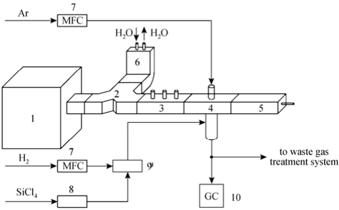
Figure 1 Sketch of apparatus for microwave plasma hydrogenation of SiCl41—microwave generator; 2—microwave ferrite circulator; 3—three-stub tuner; 4—resonator; 5—movable short circuit; 6—water load; 7—mass flow controller; 8—metering pump; 9—evaporating pot; 10—gas chromatographic analyzer

Figure 2 Sketch of quartz jacket reactor of microwave plasma
The plasma reactor is a quartz jacket (Fig. 2), which has two chambers: The upper one is a plasmainception chamber, and the lower one is a reaction chamber. The inner diameters of the plasma-inception chamber and the reaction chamber are 24 mm and 18 mm respectively. The quartz jacket sits amid the microwave resonator cavity, and the lengths of the cavity wide walls (a) and narrow walls (b) are 109.2 mm and 27.3 mm, respectively. In the plasma-inception chamber, Ar was discharged by microwave electromagnetic field and became plasma. The Ar plasma was jetted into the reaction chamber through the hole (inner diameter 2mm) in the middle of the quartz tube. In the reaction chamber, the mixture of H2and SiCl4were initiated into plasma by the Ar plasma and the microwave electromagnetic field.
2.2 Characterizations of products
The yields of SiHCl3at various hydrogenation conditions were measured via gas chromatography. The concentrations of SiHCl3and SiCl4from the outlet were determined based on the respective chromatographic peak areas using the correction normalization method.
3 RESULTS AND DISCUSSION
3.1 Plasma state and characterizations
In this study, the microwave propagation mode was TE01 in the waveguide, where the electric field was parallel to the narrow walls (b) and perpendicular to the wide walls (a). The maximum electric field Emax(kV·cm?1) was determined as follows [6]:

where PMWis the microwave incident power (kW), a and b are the respective lengths of side walls of the waveguide (cm), λ is the wavelength, and λcis the maximum wavelength when propagation is still possible (λc=2a) in the waveguide. Emaxof 0.28 kV·cm?1was retained when PMW=1.05 kW, a=10.92 cm and b=2.73 cm in the resonator.
The reactor operation principle is illustrated in Fig. 3. Curve 2 corresponds to the inception electric field (E/p) of Ar plasma at the gas pressure p, at which Ar can just be discharged and become plasma. Thus, Ar plasma cannot be incepted unless the induced electric field (E/p) is above the curve. Curve 1 corresponds to the inception electric field (E/p) of the Ar/H2mixture gases (Ar/H2molar ratio is about 1.25) plasma. Curve 4 corresponds to the minimum induced electric field for sustaining Ar plasma. Curve 3 corresponds to the minimum induced electric field for sustaining Ar/H2plasma. Curve 5 is the reactor operating line, and A and B are the inception and working points, respectively. The system pressure at the beginning of the experiment was about 1 kPa, and Ar was discharged to form plasma in the plasma chamber. The pressure was then increased to 101 kPa, and the working condition reached B, where Ar plasma could be sustained, because B is above Curve 4. The free electron generation rate (rg) in the Ar/H2mixture gas was less than the electron extinction rate (re) and Ar/H2plasma could not be sustained in general, because B is under Curve 3. However, in this case, with continuous free electron coming from the Ar plasma (assumed incoming rate was ri), equilibrium:

was gained in part of the reaction chamber, where the plasma was excited.
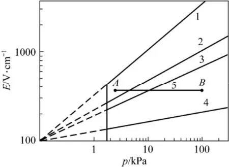
Figure 3 Diagram of the reactor operation principle
During experiments, the gas temperature was metered at the outlet of the reaction chamber. It was about 400-700 K, varied with operational conditions. Because the temperature measuring point was not in but close to the plasma, the measured Tgof plasma was just an approximate value. But it was sure that Tgwas less than 1000 K, so the plasma was in non-thermodynamic equilibrium.
This non-thermodynamic equilibrium plasma deviated significantly from the thermodynamic equilibrium state. The hydrogenation of SiCl4that occurred in this plasma provided several outstanding advantages, including mild conditions and high selectivity in producing SiHCl3(>97%).
3.2 Conversion of SiCl4
3.2.1 Effect of the ratio of H2to SiCl4
The effects of the molar ratio of H2to SiCl4were investigated first, with the Ar flow rate 2.5 L·min?1, the molar ratio of the sum of H2and SiCl4to Ar being fixed at 1.0, microwave power 1.0 kW, and system pressure 101 kPa. The mole ratio of H2to SiCl4varied from 1.4 to 4.6. In this process, the byproducts, mainly being amorphous silicon and dichlorosilane, was little in amount, and their effects could be ignored.
The SiHCl3yield increased steadily from 27% to 47% when the ratio of H2to SiCl4was increased from 1.4 to 4.6. However, the equilibrium constant given by Kp:

was kept constant (approximately 0.1), as shown in Fig. 4.
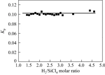
Figure 4 Kpversus the molar ratio of H2to SiCl4(reaction conditions: flow rate of Ar=2.5 L·min?1, flow rate of H2and SiCl4mixture gas=2.5 L·min?1, microwave power=1.0 kW, system pressure=101 kPa)
The SiHCl3yield is defined as the ratio of the final molar amount of SiHCl3to the initial molar amount of SiCl4. However, the mole fraction of SiHCl3in the effluent stream, defined as the ratio of the molar amount of SiHCl3to the molar sum of all substances (Ar, H2, SiCl4, SiHCl3, HCl, and so on), represents the product SiHCl3concentration, which is very important to the post-separation process.
Kpis constant in this process; thus, the optimal ratio of H2to SiCl4, at which the process gains the maximum mole fraction of SiHCl3, can be calculatedbased on the following chemical reaction of SiCl4hydrogenation:

Assume the sum of the initial molar fraction of SiCl4and that of H2was constant, c, and the initial molar ratio of H2to SiCl4denoted as χ. When the reaction reached an equilibrium state, the final molar fractions of HCl and SiHCl3both were y. Thus,
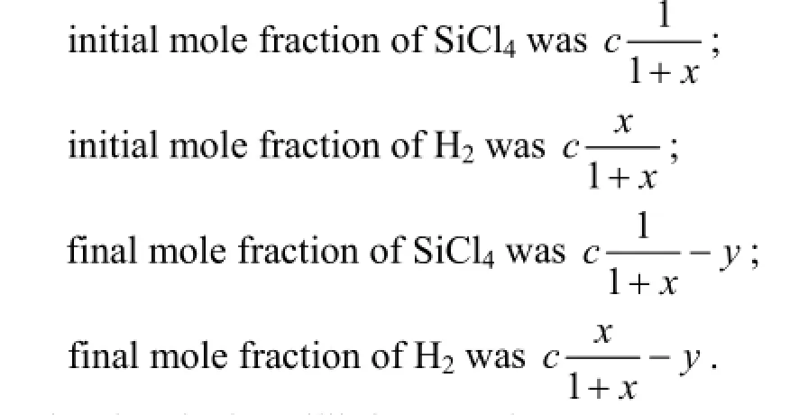
By the chemical equilibrium, we have maximum value when the initial mole fraction of SiCl4is equal to that of H2.
The reaction process was simulated in the conditions: flow rate of Ar=2.5 L·min?1, flow rate of H2and SiCl4mixture gas=2.5 L·min?1, H2/SiCl4molar ratio increasing from 0.5 to 5.0, Kpbeing 0.1. Both of calculated and experimental results are shown in Fig. 5.
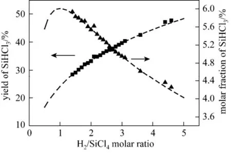
Figure 5 Yield and molar fraction of SiHCl3versus the molar ratio of H2to SiCl4(Reaction conditions are same as Fig. 4. The dash lines are calculating results, and the squares and triangles represent experimental ones)
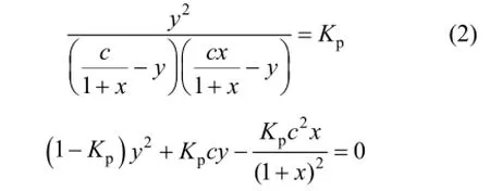
To get the maximized y, the first derivative with respect to χ

must equal to 0. This corresponds to χ=1, indicating that the SiHCl3molar fraction in products reached a
The Fig. 5 is verified that a good agreement exists between calculated and experimental values. It shows that, when reducing H2/SiCl4from 5.0 to 0.5, the yield of SiHCl3decreases monotonically, but the fraction of SiHCl3increases first, and reaches a peak in 1.0, then declines sharply.
3.2.2 Thermodynamics of the conversion
The Gibbs free energy difference (ΔG) of SiCl4hydrogenation in various temperature ranges can be calculated [14] as follows:

The reaction equilibrium constant Kpcan be determined by

The dependences of ΔG and Kpon temperature are shown in Fig. 6.
From the one-to-one correspondence of Kpand T, we may read out the actual reaction temperature T from Kpof reaction (1) obtained from experimental measurements.
In Section 3.2.1, the equilibrium constant of hydrogenation via plasma remained a fixed value, which was similar to the conventional high-temperature hydrogenation of SiCl4. This value was a steady reaction temperature related to an established equilibrium constant. The fixed value also indicates that the plasma in the regime has an invariable characteristic temperature of approximately 1500 K. The electron temperature (approximately 10000 K) [6] in the microwave atmospheric pressure plasma was much higher than the gas temperature. In this experiment, the gas temperature was about 450 K. Thus, neither the electron temperature nor gas temperature was the characteristic temperature. In this study, the characteristic temperature of plasma was called the “Reactive Temperature”, whichcharacterized the reactive potential of the plasma. The reactive temperature of plasma was determined using Kp. It has the traditional meaning as the conventional hydrogenation reaction of the same Kp.
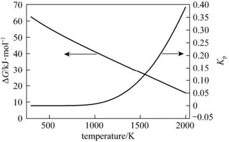
Figure 6 Dependences of ΔG and Kpon reaction temperature in reaction (1)
3.2.3 Effect of the ratio of SiCl4or H2to Ar
The effects of the ratio of SiCl4to Ar were investigated under the conditions of H2/Ar fixed at 0.8 (Ar flow rate was 2.5 L·min?1), the SiCl4/Ar ratio varied from 0.3 to 0.7, and the power of 1050 W.
The effects of the molar ratio of SiCl4to Ar on the “Reactive Temperature” of plasma are shown in Fig. 7. The “Reactive Temperature” of plasma linearly decreased with increasing SiCl4/Ar ratio.
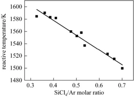
Figure 7 Influence of the SiCl4/Ar molar ratio on “Reactive Temperature”
The effects of the ratio of H2to Ar were investigated with SiCl4/Ar fixed at 0.325 (Ar flow rate at 2.5 L·min?1), the H2/Ar ratio varied from 0.8 to 1.0, and the power was 1050 W.
The effects of the molar ratio of H2to Ar on the“Reactive Temperature” of plasma shown in Fig. 8 indicate that the “Reactive Temperature” of plasma linearly decreased with increasing H2/Ar ratio. The conclusions from Figs. 7 and 8 indicate that

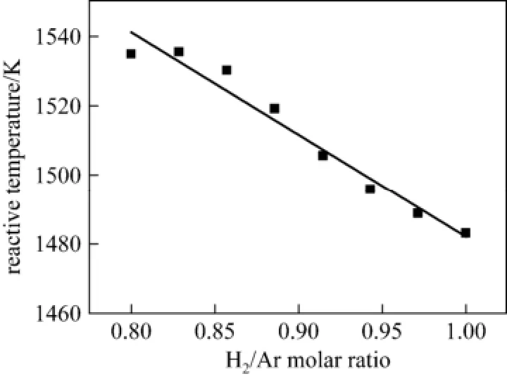
Figure 8 Dependence of “Reactive Temperature”on the H2/Ar molar ratio (SiCl4/Ar=0.325)
where α is the H2/Ar mole ratio, β is the SiCl4/Ar mole ratio, T0is the ultimate value of the plasma reactive temperature when α=0 and β=0, and k1and k2are the regression coefficients in Figs. 7 and 8, respectively. In this case, T0is about 1830 K, α=?241.6 K, and β=?295.4 K. The mole fraction of SiHCl3in the products at different ratios of the mixture of H2and SiCl4to Ar was evaluated using this mathematical model.
Section 3.2.1 concludes that the SiHCl3mole fraction in the products gains a maximum value when the initial mole fraction of SiCl4is equal to that of H2. Thus, assuming that α=β=χ/2, Eq. (3) reads

The mole fraction of SiHCl3as a function of χ varied from 0.2 to 3.0 at T0=1800 K, 1850 K, 1900 K, as shown in Fig. 9. In most experiments, T0was in the range of 1800 K to 1900 K; thus, T0was chosen as 1800 K, 1850 K, and 1900 K in this calculation.
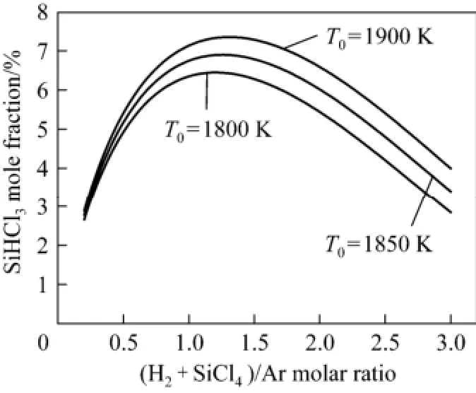
Figure 9 Influence of the ratio of H2and SiCl4to Ar on SiHCl3mole fraction of products
Figure 9 shows that the SiHCl3molar fraction increased sharply with increasing ratio from 0.3 to 1.0, reached the maximum value at ratios of approximately 1.2 to 1.4, and then gradually decreased. Thus, the optimal ratio of the sum of SiCl4and H2to Ar was 1.2 to 1.4. In two experiments above, the maximum SiHCl3molar fractions were 7.3% and 6.0% at the abscissa of 1.4 and 1.2, respectively. The result agreed well with experimental data.
3.2.4 Effect of system pressure
The dependence of the yield of SiHCl3on system pressure was investigated under the conditions that the flow rates of Ar and H2were 0.6 and 0.3 L·min?1, respectively. The flow rate of SiCl4was 0.51 g·min?1. The system pressure was increased from 13.3 to 79.8 kPa. The effects of system pressure on SiHCl3yield are shown in Fig. 10.
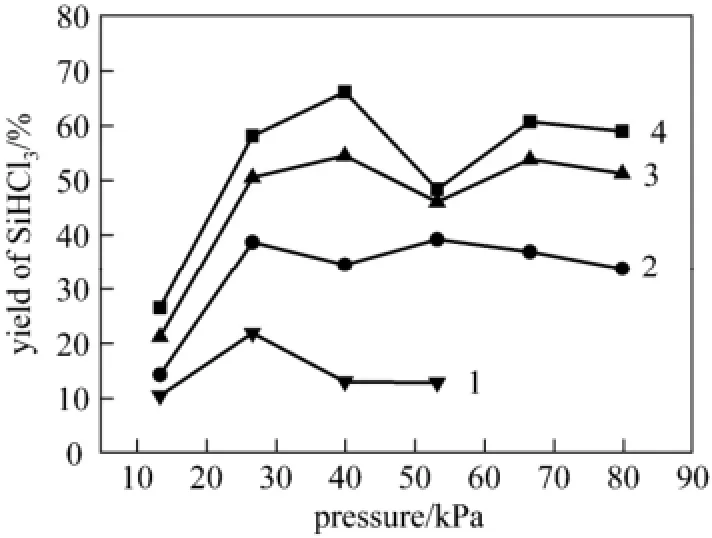
Figure 10 Influence of system pressure on SiHCl3yield incident power, P/W: 1—300; 2—480; 3—690; 4—900
The yield of SiHCl3behaves in a complex way. It increases with the pressure up to 26.6 kPa, but it displays different trend for different incident power. In general, the excessive pressure above 40 kPa seems useless.
In this work, the plasma is non-thermal plasma, and its electric temperature is about 1 eV [6], so the mean velocity of free electron (v) is about 5.9×10⁵m·s?1. H2molar fraction is about 30%, and its number concentration N is 1.9×1024mol·m?3at 26.6 kPa and 298.15 K. In this plasma system, energy transfer mainly takes place in inelastic collisions between free electrons and H2, which leads to the vibrational excitation of H2. The cross sections (σ) of vibrational excitation of H2by electron impact is 4×10?21m2[6]. The mean time interval (Δt) of electrons between the collisions is determined by


Figure 11 The effect of incidence power
where Δt=2.2×10?10s. In this work, microwave frequency is 2450 MHz, and its half period of oscillation (Th) is 2.0×10?10s.
When Δt equals to Th, a majority of electrons can collide and transfer their kinetic energy to H2molecules. (If electron could not transfer their kinetic gain from the electric field to other particles in a half period of oscillation, they will give back their kinetic energy to the electric field in the next half period.) Microwave energy is highly efficient to initiate chemical reaction. Thus, at the incident energy of 300 or 480 W, and the gas temperature of the plasma is at nearly room one, the yield of SiHCl3arrives at a peak. Otherwise when P=690 or 900 W, because of gas expansion at increasing temperature, the same value of Δt need higher pressure, and the peaks of the yield appear in about 40 kPa.
3.2.5 Effect of incident power
The dependence of the hydrogenation on incident microwave power was investigated by 2 series of experiment:
(1) Ar and H2flow rates were 3.5 and 2.9 L·min?1, respectively, the flow rate of SiCl4was 7.8 g·min?1, and the power was increased from 600 W to 1360 W.
(2) The incidence power was 700 W, and the flow rate of Ar was 2.5 L·min?1. The molar ratio of H2/SiCl4was fixed on 4.5, and the flow rate of H2was increased from 1.0 to 3.0 L·min?1, while the flow rate of SiCl4increased from 1.5 to 4.6 g·min?1.
The effects of incident power are shown in Fig. 11 in terms of feedstock gas molar energy input defined as the ratio of microwave power over the total molar flow rate of H2and SiCl4.
High energy efficiency of hydrogenation of SiCl4in non-thermodynamic equilibrium plasma requires the generation of plasma of special qualities [6]: electron temperature of about 1 eV to 3 eV and low gas temperature (<1000 K). In hydrogen plasma, a major fraction of discharge power at the electron temperature of about 1 eV to 3 eV can be transferred from the free electron to H2vibrational excitation. SiCl4hydrogenation, as an endothermic reaction, can be stimulated efficiently by H2vibrational energy. In this process, gas temperature determines the rate of the vibrational-translational (VT) relaxation. The lower the gas temperature, the lower the rate of VT relaxation, and the higher the energy efficiency translating from vibrational energy to hydrogenation the process.
Figure 11 shows that the yield of SiHCl3increased rapidly with increasing input power. Simultaneously, energy consumption decreased sharply, and then the energy consumption reached the minimum point when the feed gas molar energy input was about 350 kJ·mol?1, and the yield of SiHCl3was about 30%-40%. Afterward, the yield of SiHCl3increased slowly with input power increase, and so did the energy consumption.
At the first half of the process, the incident microwave power increase caused an increase in the electron temperature of the plasma as well as in the fraction of electron at 1 eV to 3 eV. This condition led to the increase in energy efficiency from plasma to hydrogenation, and energy efficiency gained the maximum point. However, input power further increased, and Joule heating caused the gas temperature to increase. Thus, the rate of VT relaxation became faster than before, and the energy efficiency from plasma to hydrogenation decreased.
4 CONCLUSIONS
In this study, microwave plasma using a mixture of H2and Ar gases was successfully applied for the hydrogenation of SiCl4with high efficiency and high selectivity. For the first time, the plasma exhibited a characteristic temperature related to the equilibrium constant, which was defined as the “Reactive Temperature”. A mathematical model was developed using the “Reactive Temperature” to determine the optimal experimental parameters for the hydrogenation. The optimum operation conditions were as follows: H2to SiCl4ratio of 1 and SiCl4/H2mixture to Ar ratio of 1.2 to 1.4. In this plasma, the special system pressure and incident power were required for the highest energy efficiency of hydrogenating SiCl4, while the optimum system pressure varies from 26.6 to 40 kPa depending on input power, and the optimum feed gas (H2and SiCl4) molar energy input was about 350 kJ·mol?1.
REFERENCES
1 Ding, G.L., “The influence of the mole ratio of trichlorosilane to silicon tetrachloride on polysilicon yield”, Sichuan Nonferrous Metals, (3), 14-19 (1998). (in Chinese)
2 Liang, J.W., “The production technology of eletronic grade polycrystalline silicon”, Chin. Eng. Sci., 2 (12), 34-39 (2000). (in Chinese)
3 Gusev, A.V., Kornev, R.A., Sukhanov, A.Y., “Preparation of trichlorosilane by plasma hydrogenation of silicon tetrachloride”, Inorg. Mater., 42 (9), 1023-1026 (2006).
4 Sarma, K.R., Rice, Jr. M.J., “High pressure plasma hydrogenation of silicon tetrachloride”, US Pat., 4309259 (1982).
5 Wu, Q.Y., Chen, H.B., Li, Y.L., Tao, X.M., Huang, Z.J., Shang, S.Y., Yin, Y.X., Dai, X.Y., “Preparation of trichlorosilane from hydrogenation of silicon tetrachloride in thermal plasma”, Inorg. Mater., 46 (3), 251-254 (2009).
6 Fridman, A., Plasma Chemistry, Cambrige University Press, New York (2008).
7 Jasinski, M., Dors, M., Mizeraczyk, J., “Destruction of freon HFC-134a using a nozzleless microwave plasma source”, Plasma Chem. Plasma Proc., 29, 363-372 (2009).
8 Wu, L.F., Ma, Z.B., He, A.H., Wang, J.H., “Decomposition of silicon tetrachloride by microwave plasma jet at atmospheric pressure”, Inorg. Mater., 45, 1403-1407 (2009).
9 Jasimski, M., Dors, M., Mizeraczyk J., “Production of hydrogen via methane reforming using atmospheric pressure microwave plasma”, J. Power Sources, 181, 41-45 (2008).
10 Uyama, H., Matsumoto, O., “Synthesis of ammonia in high-frenquency discharges. II. Synthesis of ammonia in a microwave discharge under various conditions”, Plasma Chem. Plasma Proc., 9 (3), 421-432 (1989).
11 Oumghar, A., Legrand, J.C., Diamy, A.M., Turillon, N., “Methane conversion by an air microwave plasma”, Plasma Chem. Plasma Proc., 15 (1), 87-107 (1995).
12 Hemawan, K.W., Grotjohn, T.A., Reinhard, D.K., Asmussen, J.,“Improved microwave plasma cavity reactor for diamond synthesis at high-pressure and high power density”, Diam. Relat. Mater., 19, 1446-1452 (2010).
13 Grotjohn, T., Liske, R., Hassouni, K., Asmussen, J., “Scaling behavior of microwave reactors and discharge size for diamond deposition”, Diam. Relat. Mater., 14, 288-291 (2005).
14 National Institute of Standards and Technology, “Silicon tetrachloride”, In: Gas Phase Thermochemistry Data, NIST Chemistry Web-Book, Material Measurement Laboratory, 1970 [2011-09-09], http://webbook.nist.gov/cgi/cbook.cgi?ID=C10026047&Units=ST& Mask=1#Thermo-Gas.
Received 2012-02-09, accepted 2013-03-16.
* To whom correspondence should be addressed. E-mail: wgzhang@mail.ipe.ac.cn
 Chinese Journal of Chemical Engineering2014年2期
- Chinese Journal of Chemical Engineering的其它文章
- Large-eddy Simulation of Ethanol Spray-Air Combustion and Its Experimental Validation*
- Optimization of Two-species Whole-cell Immobilization System Constructed with Marine-derived Fungi and Its BiologicalDegradation Ability*
- Numerical Simulation of Oxy-coal Combustion for a Swirl Burner with EDC Model*
- Performance of EDAB-HCl Acid Blended System as Fracturing Fluids in Oil Fields*
- Kinetic and Thermodynamic Studies of Acid Scarlet 3R Adsorption onto Low-cost Adsorbent Developed from Sludge and Straw*
- Synthesis of Sub-micrometer Lithium Iron Phosphate Particles for Lithium Ion Battery by Using Supercritical Hydrothermal Method
