LABORATORY STUDIES ON WAVE FORCE OF COASTAL STRUCTURES MADE OF FLAT GEOTUBES*
LIN Gang, SHU Yi-ming, LU Xin, DAI Lin-jun, YU Xin-zhou, ZHANG Xian-lei, YI Jing-rong
College of Water Conservancy and Hydropower Engineering, Hohai University, Nanjing 210098, China, E-mail: lingang9804@163.com
LABORATORY STUDIES ON WAVE FORCE OF COASTAL STRUCTURES MADE OF FLAT GEOTUBES*
LIN Gang, SHU Yi-ming, LU Xin, DAI Lin-jun, YU Xin-zhou, ZHANG Xian-lei, YI Jing-rong
College of Water Conservancy and Hydropower Engineering, Hohai University, Nanjing 210098, China, E-mail: lingang9804@163.com
(Received January 6, 2011, Revised March 23, 2011)
Flat geotubes are widely used for coastal structures such as seawalls, breakwaters and sightseeing groins, etc.. However, the understanding of the stable mechanism involved in the wave-structure interactions should be deepened, and one of the important work is to clarify the stress state of the structure under the wave action. In this article, wave force acting on coastal structures made of flat geotube is experimentally investigated. The required drag, inertia and lift coefficients are especially analyzed from the results of hydraulic model experiments specially designed for geotube structure. Several types of structures made of flat geotubes under wave action have been tested in order to understand the stress state of the geotube fixed to force transducer within different structures. Experimental results show that the wave-induced forces on the instrumented geotube are markedly influenced by wave elements. Meanwhile, the magnitude of horizontal force of adjoining geotube is different at the same time.
flat geotube, wave force coefficients, inertial force, drag, lift, coastal structure, hydraulic model experiment
Introduction
There is a long coastline along the East and South of China, and potamic shoreline are also widely distributed inland. Many coastal structures such as seawalls, artificial reefs, speedway and even reservoir have been built around these lines. These structures are more and more used instead of hard coastal framework made of concrete or rubble materials[1]. And flat geotubes are widely adopted. In recently years, many coastal structures have been successful constructed made of flat geotube. However there is no ready-made theory or formulae available for the hydraulic stability of flat geotube structures, which is used to accounting for the process affecting the stability of structure. The most important of studying the stability of structure is to analyze wave forces acting on flat geotubes.
Based on the previous investigations, a new experiment has been designed, in order to study the characteristics of wave-structure interaction[2-4]. A geotube fixed to force transducer, which is placed in several types of geotube configurations, is used to gain the drag, inertia and lift wave force in the wave action and study the stress state of different geotube structures in combination wave elements. By using the least square method, the drag, inertia and lift coefficients CD, CIand CLare derived in this article.
1. Theoretical formulae
1.1 Wave force and coefficient formulae
According to the Morison equation, the waveinduced horizontal force on the geotube structure is given by

where ρ is the density of water, CDthe drag force coefficient which reflects on the shape and material of the flat geotube, CIthe inertia force coefficient, Asthe cross-section area of geotube normal to the water current, V the volume of the geotube, and u( z, t) the horizontal particle water current velocity in the vicinity of the geotube structure.
The wave-induced lift force is as follows

where CLis the lift force coefficient, ATis the plan form area of the flat geotube.
In the hydraulic model experiment, the drag and inertia force coefficients are derived with the least square method. The related formulae are:
Drag force coefficient

Inertia force coefficient
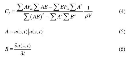
where Fmis the actual measurement horizontal force of the geotube in the experiment.
The lift force coefficient is given as

where u( z, t)maxis the maximum of the horizontal particle water current velocity in the vicinity of the geotube structure.
1.2 Water particle acceleration

When d/L is smaller than 1.0, the shallow water assumption could be employed, so the horizontal particle velocity u is equal to the wave celerity as follows

where g is the acceleration of gravity, d the water depth at the measurement point and L the wave height.
Further, the horizontal water particle acceleration can be expressed as

where uiand ui?1denote the horizontal velocities in the vicinity of the geotube structure measured at time instants tiand ti?Δt respectively.
2. Experimental setup
Since there is no literature about the drag, inertia and lift force and coefficient for flat geotube applied to coastal structure, extensive experiments are necessary and feasible to gain the real information of the geotube structure under the wave action[8,9].
The experiments were performed in the wave flume of the Key Laboratory of Coastal Disaster and Defense, Ministry of Education, at Hohai University. The flume was 80 m long, 1.0 m wide and 1.5 m high. Wave-maker was installed at one end of the flume, and the system with negligible wave reflection was fixed on the other end. The flume was divided in two sections with width of 0.5 m and 0.3 m respectively, where one part is used to set geotube structure model and the other used for eliminating the wave reflection. The plan view of the wave flume is shown in Fig.1. According to the dimensions of the wave flume, the model scale 1:30 was selected.
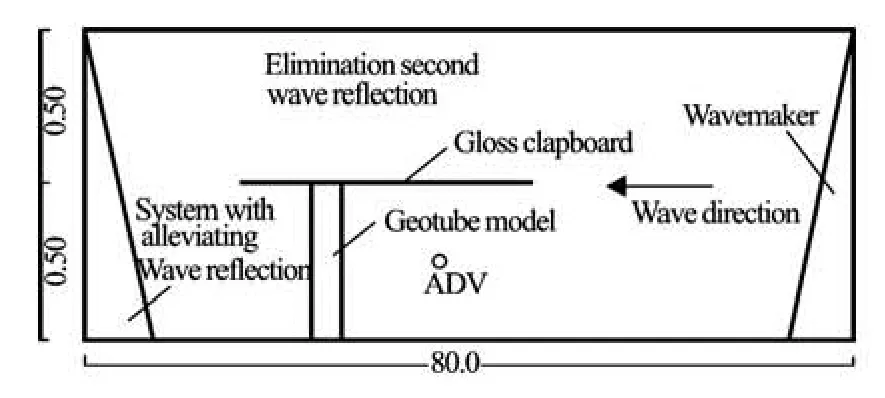
Fig.1 Plan view of the wave flume (m)
The measurement of the wave-induced pressure was conducted with the force transducer controlled by the DJ800 multifunctional monitoring system, which was developed by China Institute of Water Resources and Hydropower Research. The measuring range of force transducer varied from –2 kPa to 10 kPa and the error was ±0.3% F.S.
An instrumented geotube as well as several other similar ones were placed in different configurations in the flume and the structures were impacted by wave element conditions designed. The measured geotube was instrumented with force transducers in order to obtain the horizontal and uplift wave-induced forces of the geotube at every cycle of wave, which was made of wood and wrapped with the same geotextile as other geotubes used in experiments, so as to modify the same roughness of geotubes as practical projects.The dimensions of the instrumented geotube were 0.50 m long, 0.42 m wide and 0.02 m high. Others geotubes were filled with sand at an approximate dry density of 1 650 kg/m3, and the filling ratio was about 80% of the cube-shaped volume of the geotube without considering the deformation of the geotextile flat geotube[10]. The instrumented geotube is shown in Fig.2.
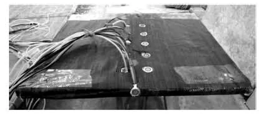
Fig.2 Instrumented flat geotube made of wood, covered with geotextile (fixed with force transducers)
In the experiment, the wave-induced water particle velocity in the vicinity of the geotube structure was obtained by the Nortek Vectrino Velocimeter. The velocimeter precision was ±0.001 m/s.
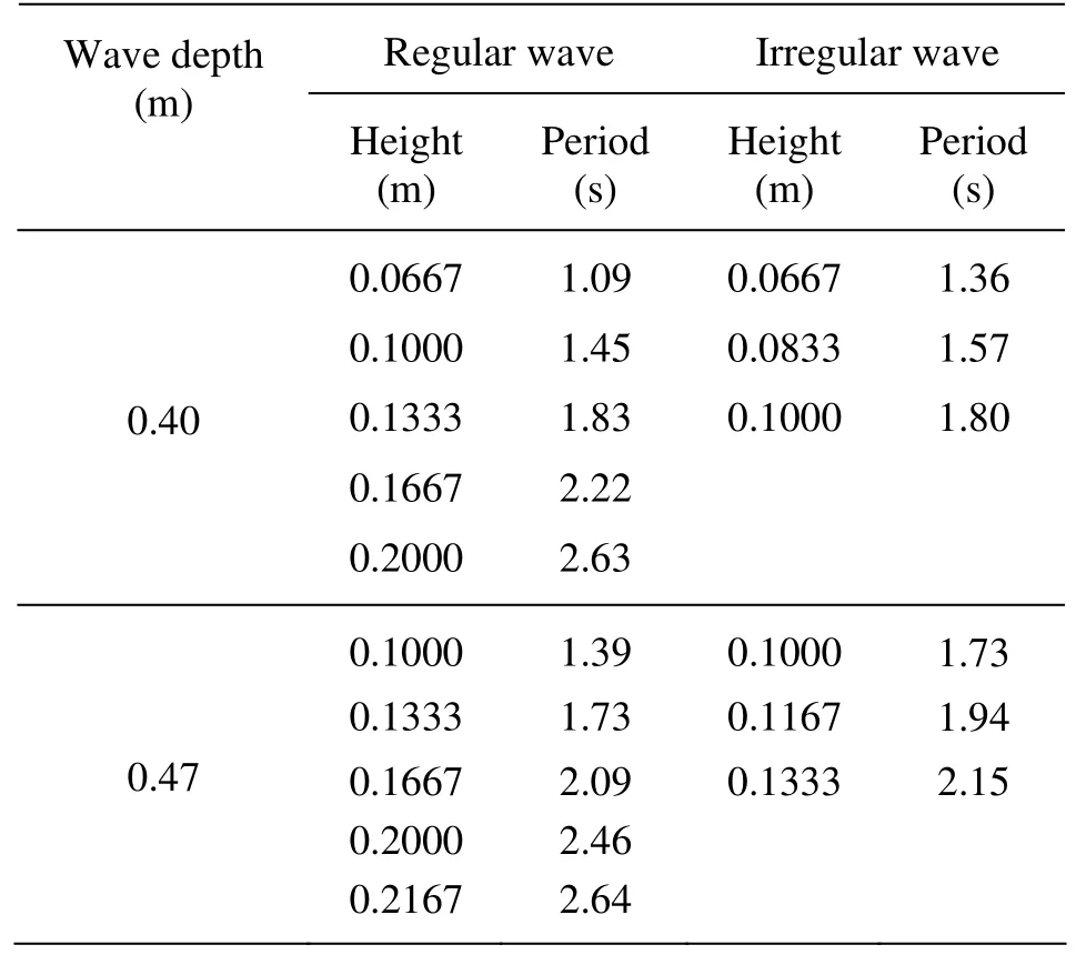
Table 1 Parameters in experiments ( H / L =1/25)
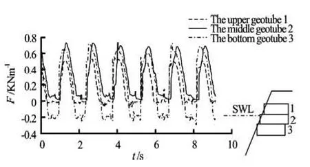
Fig.3 Wave-induced horizontal force on the still water level (d=0.40 m, T=1.45 s, H=0.10 m)
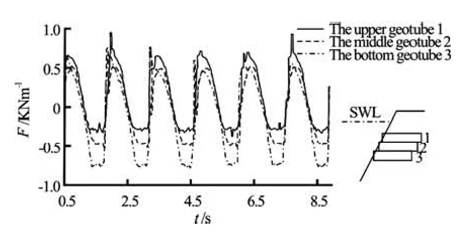
Fig.4 Wave-induced horizontal force under the deep water (d=0.47 m, T=1.39 s, H=0.10 m)
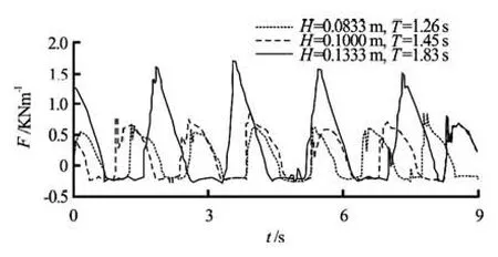
Fig.5 The wave-induced horizontal forces for different wave heights (d=0.40 m)
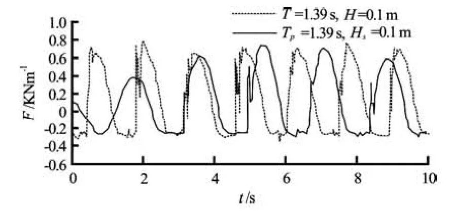
Fig.6 The wave-induced horizontal forces in regular and irregular wave (d=0.47 m)
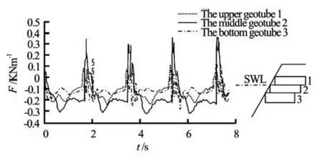
Fig.7 The wave-induced uplift forces of geotubes at different positions (d=0.40 m, T=1.83 s, H=0.1333 m)
The geotube structures were subjected to both regular and irregular waves with wave heights (or significant wave height) varying from 0.06 m to 0.22 m and wave periods (or spectrum peak period) from 1.09 s to 2.64 s by the cases of H/L (1:25) and two constant water depths (0.40 m and 0.47 m). The parameters are shown in Table 1.
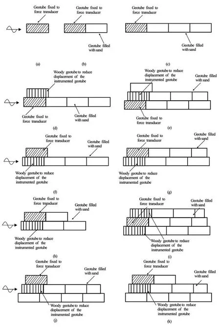
Fig.8 The cross section of 11 different configurations of flat geotube in experiment
In the experiment, while one geotube structure model was performed by wave series, the wave forces of geotube and flow velocity of water particle were recorded. Then by changing the models, the corresponding wave forces and velocity were measured.
3. Results and discussions
3.1 The horizontal and lift forces of flat geotube
The wave-induces forces on geotubes in different wave conditions were systematically measured. The main results of the horizontal and lift forces on geotube are summarized as follows:
(1) The wave-induced horizontal force on the geotube just placed on the still water level reaches its maximum. The wave-induced horizontal forces decreases with increasing depth of the geotube is placed from the still water to the sea bed downwards, which is shown in Figs.3 and 4.
(2) For the same parameters other than wave height, the wave-induces horizontal forces on the geotube increases with increasing wave height, which is shown in Fig.5.
(3) Except for several high wave forces, the irregular wave-induced forces on the geotube is smaller than the regular wave-induced ones, as shown in Fig.6. However, the negative influence of the irregular wave force on the stability of the structure made of flat geotube should be noticed. The displacement of the upper geotube took place before the structure instability occurring based on previous research[11,12]. And just the several high wave forces may make the displacement of the upper geotube happen.
(4) Because of the influence of large plain area and filled material of the geotube, the lift forces on the geotube are irregular. The general tendency is that the wave-induced lift force on the upper geotube is greater than the lower one. This is in line with the results that the upper geotube is more easily unstable in the previous studies. The lift force on the geotube is shown in Fig.7.
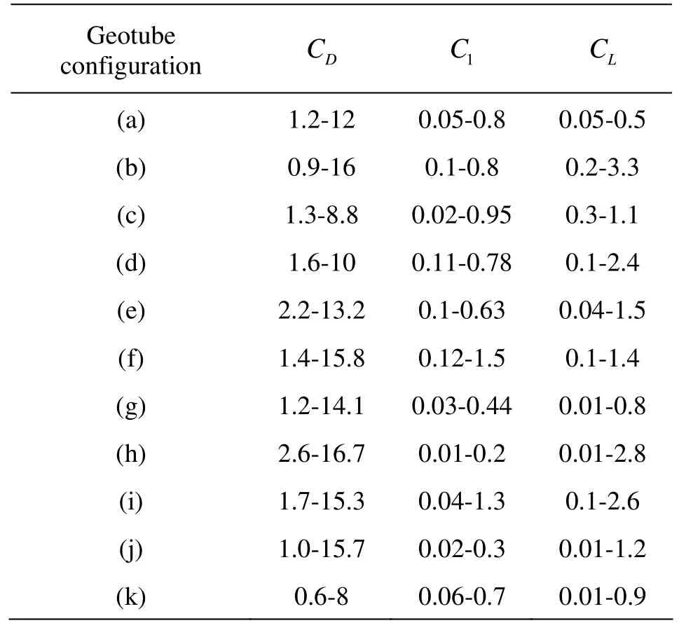
Table 2 Summary of drag, inertia and lift force coefficients CD, CIand CL
3.2 The drag, inertia and lift coefficients CD, CIand CL
In the experiment, the instrumented flat geotube placed in multilayer structures were studied. The partial cross sections of geotube structures are shown in Fig.8.
For each model test, the drag, inertia and lift force coefficients are derived with the least square method. Based on the experimental data of horizontal, lift force and water particle velocity in the vicinity of the geotube structure[13,14], the results for the drag, inertia and lift force coefficients are shown in Table 2.
Table 2 shows that the drag force coefficient has the largest values and the inertia force coefficient is the smallest one in the three coefficients. From the experiment, the viewpoint is also confirmed that the drag force is dominated over the stability of flat geotube structure. The magnitudes of the drag, inertia and lift force coefficients and their varying trends are similar to the results of Recio and Oumeraci. It indicates that the results of this experiment are believable.
From the experiment results, it is also found that the force coefficients are closely related to water conditions investigated and the effect of the Reynolds number is strong, which need to be studied further.
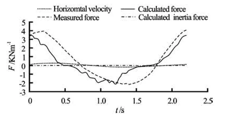
Fig.9 Comparison of the measured and calculated horizontal wave force (d=0.40 m, H=0.1667 m, T=2.22 s, CD=8.8, CI=0.74)
After obtaining the drag, inertia and lift force coefficients CD, CIand CLfrom the measured forces, velocities and derived accelerations, the calculation of the wave forces can be carried out. Figure 9 shows the examples of measured and calculated horizontal wave forces. The inertia forces term is also shown in Fig.9. It is shown that the measured and calculated forces have the similar tendency, and the inertia force is much smaller than the drag force in the experiment.
Figure 10 shows the comparison of measured and calculated results for uplift wave forces. It can be seen that the values of measured and calculated forces agree quite well in spite of existing wave phase difference which is probably resulted from the discrepancy of fixed calculated period in the process of calculationand varying ones under experiment.
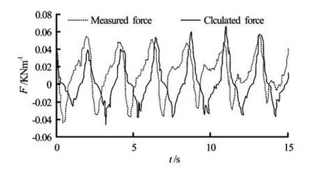
Fig.10 Comparison of the measured and calculated uplift wave force (d=0.40 m, H=0.1667 m, T=2.22 s, CL=0.6)
4. Conclusions
Structures made of flat geotubes have been experimentally investigated[15,16]. There are a variety of configurations for placing the instrumented flat geotube, but only several representative structures were chosen to test. The horizontal and lift forces were measured, and the drag, inertia and lift force coefficients were derived from the measured forces, velocities and accelerations.
Based on the obtained results, the following conclusions could be reached:
(1) The experiment has given some new information on the characteristics of the forces on the structure made of flat geotubes impacted by wave.
(2) The wave force of coastal structures made of flat geotubes is influenced by the wave element, structure styles and the position of the instrumented geotube in configurations, and the drag, inertia and lift force coefficients are different correspondingly.
(3) The horizontal drag force is apparently dominated over the flat geotube.
(4) In order to study the stability of the structures made of geotube, it is important to obtain the drag, inertia and lift coefficients. Based on the result of this article, we can conclude that it is reasonable and feasible to derive the force coefficients CD, CIand CLof flat geotube structure with Morison’s Equations.
[1] RECIO J., OUMERARIC H. Effect of deformations on the hydraulic stability of coastal structures made of geotextile sand containers[J]. Geotextiles and Geomembrances, 2007, 25(4-5): 278-292.
[2] LI Yong, LIN Mian. Wave-body interactions for a surface-piercing body in water of finite depth[J]. Journal of Hydrodynamics, 2010, 22(6): 745-752.
[3] ZHANG W., TAN J. 2-D finite element analysis and stability calculation of geotextile tubes[C]. 8ICG 8th International Geosynthetics Conference Proceedings. Yokohama, Japan, 2006, 769-772.
[4] MARTH R., MUELLER G. and WOLTERS G. Damages of blockwork coastal structures due to internal wave impact induced pressures[C]. Proceedings of the International Coastal Symposium. Hafnafjordur, Iceland, 2005.
[5] RECIO J., OUMERARIC H. Process based on stability formulae for coastal structures, made of geotube[J]. Coastal Engineering, 2009, 56(5-6): 632-658.
[6] HUA Lei-na, YU Xi-ping. Element-free Galerkin method for response of stratified seabed under wave action[J]. Journal of Hydrodynamics, 2009, 21(4): 550-556.
[7] RECIO J., OUMERARIC H. Processes affecting the hydraulic stability of coastal revetments made of geotextile sand containers[J]. Coastal Engineering, 2009, 56(3): 260-284.
[8] SHU Y. M. Field experiment for dike soil at Yangtze River Estuary[C]. Proceedings of the International Symposium on Engineering Practice and Performance of Soft Deposits. Osaka, Japan, 2004, 1: 457-461.
[9] PILARCZYK K. W. Geosynthetics and geosystems in hydraulic and costal engineering[M]. London: Taylor and Francis, 2000.
[10] ZHANG Jun-ping. Use of stuffed geotextile container in phase one of ShenHua Port in Huanghua[J]. China Harbour Engineering, 2002, 4(2): 46-48(in Chinese).
[11] ZHU C. R., SHU Y. M. and JIANG J. H. Study on the experiment of unarmored flat geotube dike under wave action[C]. Proceeding of the 4th Asia Regional Conference on Geosynthetics. Shanghai, 2008, 625-629.
[12] ZOU Lin, LIN Yu-feng. Force reduction of flow around a sinusoidal wavy cylinder[J]. Journal of Hydrodynamics, 2009, 21(3): 308-315.
[13] VERNUGOPAL V., VARYANI K. and BARLTROP N. Wave force coefficients for horizontally submerged rectangular cylinders[J]. Ocean Engineering, 2006, 33(11-12): 1669-1704.
[14] HUI Er-qing, HU Xing-e and JIANG Chun-bo et al. A study of drag coefficient relanted with vegetation based on the flume experiment[J]. Journal of Hydrodynamics, 2010, 22(3): 329-337.
[15] LIN Gang. Test and study on dike structure with flat geotube in the action of wave[D]. Master Thesis, Nanjing: Hohai University, 2005(in Chinese).
[16] XIA Yan, SHU Yi-ming and YANG Xiang-quan. Laboratory study on the factor influence flat geotube dike stability under wave impact[J]. Advances in Science and Technology of Water Resources, 2009, 29(1): 220-222, 238(in Chinese).
10.1016/S1001-6058(10)60181-3
* Project supported by the National Natural Science Foundation of China (Grant No. 51179065), the National Science and Technology Support Plan (Grant No. 2012BAB03B02).
Biography: LIN Gang (1978-), Male, Ph. D. Candidate
SHU Yi-ming, E-mail: shym@hhu.edu.cn
 水動(dòng)力學(xué)研究與進(jìn)展 B輯2011年6期
- 水動(dòng)力學(xué)研究與進(jìn)展 B輯的其它文章
- COUPLING EFFECT OF SEEPAGE FLOW AND RIVER FLOW ON THE BANK FAILURE*
- EXPERIMENTAL STUDY ON SEDIMENT RESUSPENSION IN TAIHU LAKE UNDER DIFFERENT HYDRODYNAMIC DISTURBANCES*
- LATTICE BOLTZMANN METHOD SIMULATIONS FOR MULTIPHASE FLUIDS WITH REDICH-KWONG EQUATION OF STATE*
- NUMERICAL STUDY OF HYDRODYNAMICS OF MULTIPLE TANDEM JETS IN CROSS FLOW*
- NUMERICAL SIMULATION OF FLOW OVER TWO SIDE-BY-SIDE CIRCULAR CYLINDERS*
- SIMULATIONS OF FLOW INDUCED CORROSION IN API DRILLPIPE CONNECTOR*
